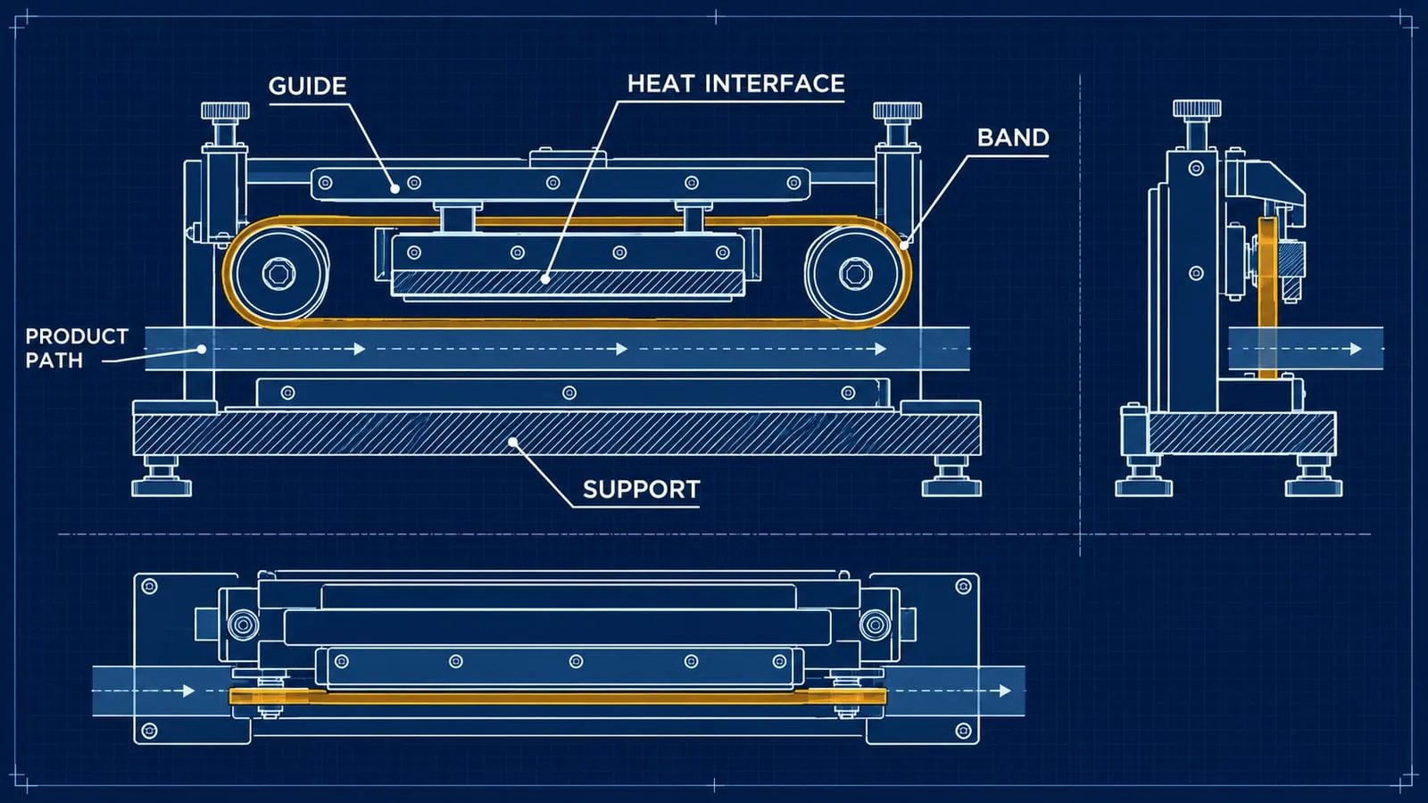
The phrase “automatic band sealer machine” describes an equipment arrangement, not a universal replacement part. An automatic line may use a moving heat-seal band, guides, a heated contact area, support surfaces and controls that are specific to the fitted station. The part that needs replacing must match those interfaces.
For UK packaging engineers, maintenance technicians, production managers and procurement teams, the useful question is not only which machine is installed. It is which component is fitted, where it sits, what it touches, and what evidence can be checked before an order is placed.
What the machine term tells you
Automatic does not mean universal
The word “automatic” describes how the packaging process is operated. It does not identify the band width, heater arrangement, guide profile, connection or mounting pattern. Two lines can use similar equipment names while carrying different components.
Start with the manufacturer, model, serial or asset reference. Add a photograph of the complete machine and a close image of the sealing station. If the line has more than one sealing head, label the photographs so that the component can be traced back to the correct position.
The machine reference is useful context for a heat-seal bands service, but it should not be used as a substitute for a component description. A supplier needs to know what is fitted before compatibility can be assessed.
Identify the sealing station
Record whether the band is used on a horizontal or vertical path, whether the product or film passes between the band and a support, and whether the station has more than one heated contact area. Note the direction of travel and the point where material enters and leaves.
A simple annotated photograph is often enough to show the position. The aim is to distinguish the sealing station from upstream feeding, coding, cutting or conveying equipment. Do not assume that every band visible on a line is a heat-seal band.
Map the automatic sealing path
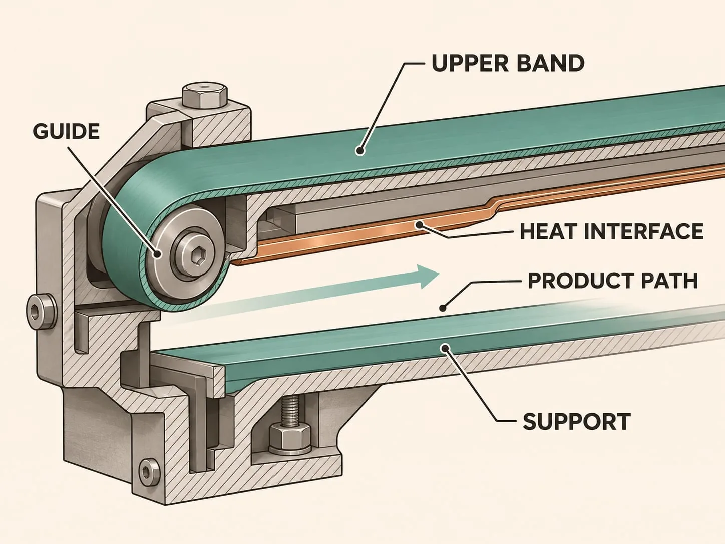 The sealing path should be described from the material route outward. Mark the product path first, then show the band, guide, heat interface and support that define the contact area. This helps separate an active sealing component from a cover, guard or transport belt.
Follow the band and guide
Record the parts that keep the band in position, including visible rollers, guide faces, retaining features and changes in direction. If the band passes behind a guard, take photographs from both sides when the equipment has been made safe under the site procedure.
An endless band may have a longer route than the portion that contacts the material. Its overall path, support and connection arrangement can matter just as much as the visible sealing point. A replacement that matches one visible dimension may still be unsuitable if the route or retaining method is different.
Mark the heat interface and support
Identify the surface that transfers heat and the surface that supports the material or band. These may be separate parts, and the contact face may use a protective layer. Where the fitted design calls for it, PTFE coating or PTFE heat-seal tape can form part of the component discussion. The required treatment must be confirmed from the assembly and operating conditions.
Do not infer a temperature, pressure or speed from an illustration or from the machine category. Record the values already confirmed by the machine documentation or site process, and leave unknown values marked as unknown.
Build a component evidence pack
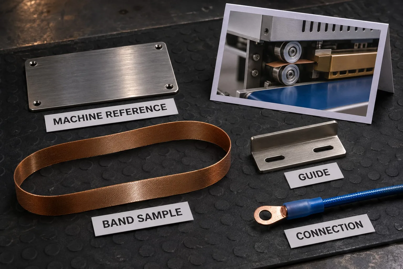 An evidence pack makes a technical enquiry easier to review. Keep the machine reference, photographs, measurements and any removed part together under one temporary part name if a manufacturer number is not available.
Photograph the part in context
Take one overall photograph of the equipment, one image showing the sealing station, and close views of the band edge, guide, heat interface and connection. Use the same orientation in each image where possible. If a guard or cover hides an interface, say so rather than guessing what is behind it.
If the component has been removed, label which side faced the product path and which side faced the guide or support. Keep fasteners, terminals and cover materials with the part until it has been identified. A photograph of an old part is useful evidence even when the part is damaged.
Record measurements in millimetres
Use metric units and state what each measurement means. Depending on the component, the useful record may include:
- band width, thickness and visible loop or run dimensions;
- guide length, width, profile and mounting-hole positions;
- heat-interface length and the position of retaining features;
- lead exit, terminal type and connection orientation; and
- clearances to adjacent supports or guards.
Do not replace a missing measurement with a typical value. If the component cannot be measured safely while installed, mark the value as unknown and provide a clear photograph or removed-part reference instead. A ruler can provide scale, but it should not cover the edge or connection that needs to be identified.
Preserve the machine reference
Keep the maker’s plate, asset tag, maintenance note or stores reference with the image set. Remove or obscure unrelated personal information before sending a photograph. If the line has two similar stations, use a separate reference for each and record which one needs attention.
This separation is especially useful where a request could involve heat-seal elements, an endless band, a coated contact surface, or sealing jaws and bars. The component category should follow the evidence, not the wording used on an old purchase order.
Check compatibility before ordering
Match the component to the application
Compatibility is a combination of machine context and component evidence. Give the supplier the equipment maker and model, the sealing-station position, the product or film path, measured features, connection details and photographs. Include the process information that is already confirmed by the machine documentation.
Heat-seal elements and bands can be associated with different packaging applications, including impulse sealing, vacuum packing, VFFS and flow-wrap equipment. That does not make parts interchangeable. A request for an automatic band sealer component should identify the actual band route and contact arrangement rather than relying on a broad application label.
Heat Seal Components supplies components and compatibility guidance, not complete sealing machines. Where an existing assembly needs a made-to-fit component, custom heat-seal element support is more useful when the enquiry includes a drawing, a sample or a complete measurement set.
Separate the band from nearby equipment
Automatic lines can include conveyors, product guides, coding units and cutting equipment close to the sealing station. A nearby belt may transport the pack without forming the seal. A metal bar may be a guard, support or sealing jaw rather than a heating element.
Use the product path and the contact surface to describe the part. If the line has vacuum, gas flushing or another process stage, record where it occurs without implying that the band itself performs that function. This prevents a machine description from expanding into an unsupported product claim.
Plan maintenance around the fitted machine
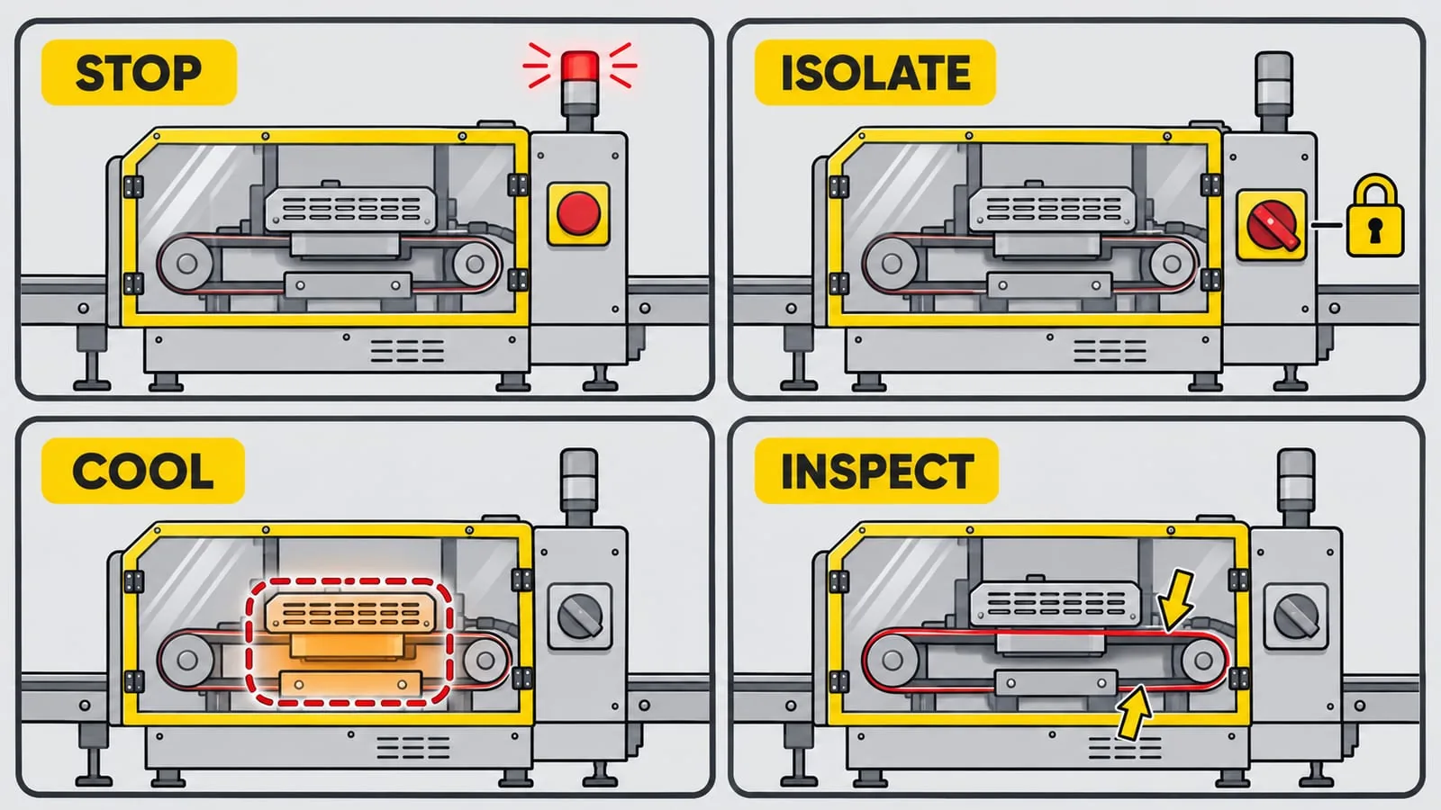 Maintenance records should relate to the actual equipment and the risks present on site. HSE guidance on packaging machinery highlights trapping points, guarding and the need for safe systems during cleaning, maintenance and blockage clearing.
Stop, isolate and allow cooling
Before touching a band, guide or heat interface, follow the site’s procedure for stopping and isolating the equipment. Consider electrical, pneumatic, hydraulic and other energy sources that could start movement or cycle the station. Prevent inadvertent reconnection where the procedure requires it, release stored energy, and allow hot components to cool.
HSE’s maintenance guidance says maintenance should be planned and carried out by competent people, with moving plant isolated or locked and hot components given time to cool. This article does not replace the manufacturer’s instructions, site risk assessment or safe system of work.
Record condition without diagnosing the cause
Describe what is visible: fraying, a polished contact area, contamination, a damaged cover, loose fasteners, a displaced guide or a change in edge shape. Record the location and photograph the observation. Do not convert an observation into a fault diagnosis unless a competent person has investigated it.
HSE advises that inspection should reflect risk assessment, manufacturer’s recommendations and the conditions in which the equipment is used. The inspection guidance also explains that records should be kept where an inspection is required. A component note can support this process, but it is not a replacement for the site’s maintenance system.
When custom component support is appropriate
Use a sample or drawing where possible
A clear sample, drawing or complete measurement set is valuable when a component has no readable part number. Include the interfaces that must remain unchanged, such as the guide contact, mounting face, retaining method and electrical connection. If the band is part of a matched assembly, identify the companion parts rather than sending an isolated description.
The confirmed Heat Seal Components offer covers heat-seal elements and wires, endless bands, custom impulse elements, PTFE coating and heat-seal tape, sealing jaws and bars, and compatibility guidance for vacuum packers, impulse sealers, VFFS and flow-wrap equipment. The evidence determines whether a specific request fits that offer.
Keep a repeatable procurement record
Save the final photographs, measurements, equipment reference, station label and supplier correspondence under one part reference. When a repeat order is needed, compare the new requirement with the same evidence rather than recreating the specification from memory. If the line or packaging material changes, update the record before reordering.
For a component review, contact Heat Seal Components with the machine reference, sealing-station photographs, measurements and any available drawing or sample. Clear evidence makes it easier to distinguish an automatic band requirement from a different heating element, tape, jaw or guide requirement.