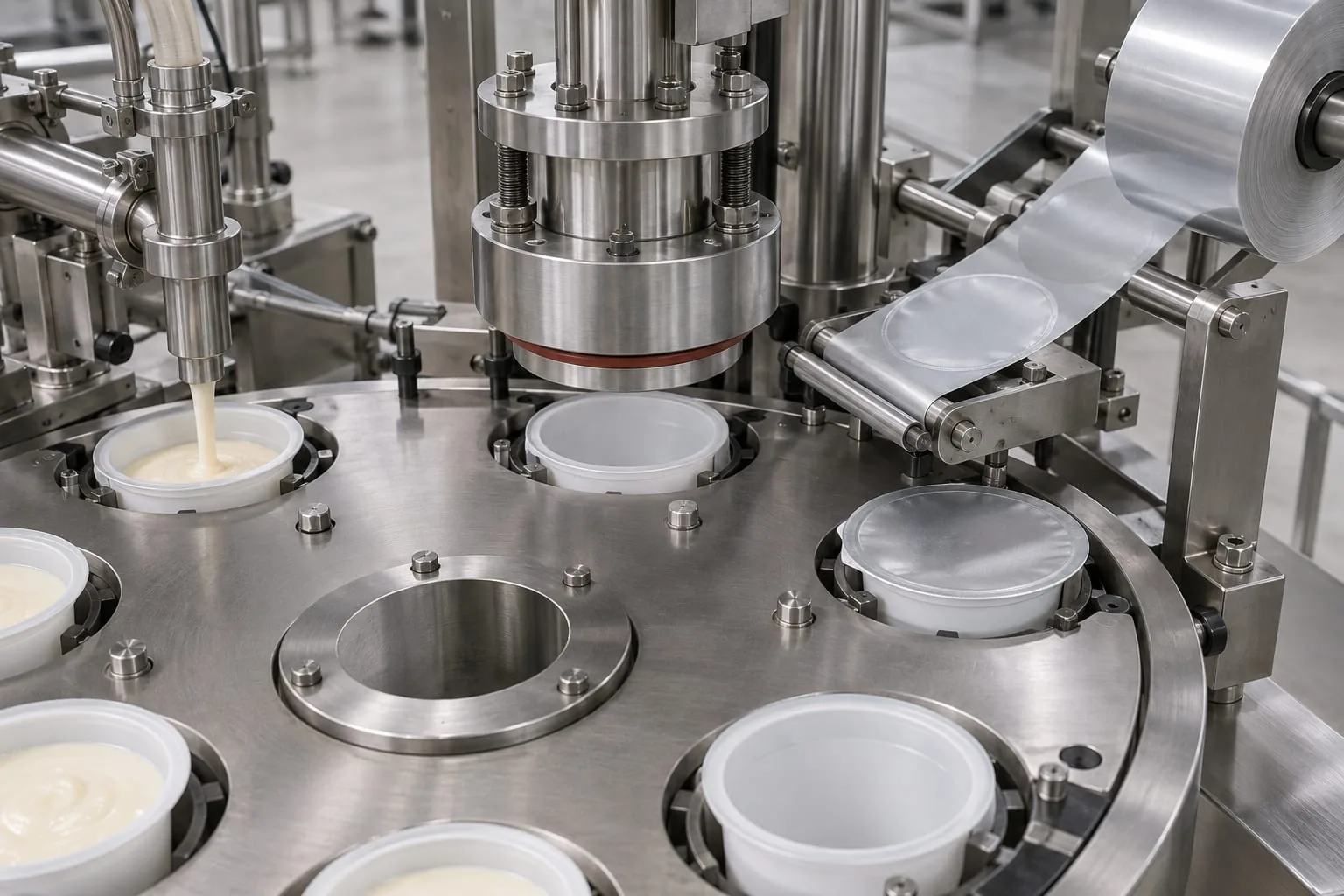
An automatic cup filling and sealing machine combines several controlled stages: a cup is presented, product is dispensed, a lid is positioned and a sealing head applies the conditions needed to close the pack. When the seal becomes unreliable, replacing a single component is rarely a matter of matching a part by appearance. The cup rim, lid material, support, heated interface and machine timing all need to work together. This guide explains what to check before sourcing replacement heat-seal elements, sealing jaws or related parts.
What the cup filling and sealing process involves
Filling and sealing are linked stages
A typical line indexes cups through a sequence of operations rather than treating filling and sealing as separate jobs. A carrier or pocket holds the cup in position, a dosing point adds the product, a lid is dispensed or unwound, and a heated head closes the lid against the rim. The exact arrangement varies by format, but the sealing station depends on the earlier stages presenting a clean, correctly positioned cup.
Tetra Pak’s description of one cup-filling application illustrates this relationship: cup control, filling, lid handling and a temperature-, pressure- and time-controlled sealing head are part of the same process. That is useful context, but it is not a universal specification. Use the machine builder’s documentation for the actual sequence and settings on the line being assessed.
Treat the machine name as an application clue
The phrase automatic cup filling and sealing machine identifies an application, not a standard replacement part. Two lines may use different cup diameters, rim profiles, lid constructions, head geometries, support rings and indexing arrangements while performing a similar job. The practical question is therefore not simply, “Which machine is this?” It is, “Which surfaces meet during the seal, and what part controls each surface?”
For component sourcing, start with the sealing assembly. A visual inspection can show whether the head is distorted, marked or contaminated, but it cannot confirm electrical compatibility or the correct replacement profile on its own.
Which components affect the cup seal
Cup carrier and rim support
The carrier keeps the cup concentric and at the intended height while the sealing head closes. A loose pocket, worn support or incorrect format change part can leave the rim low, tilted or off-centre. The head may still travel through its normal stroke, yet the contact ring will not be loaded evenly.
Check the cup support with the correct format tooling fitted. Look for rocking, visible gaps, damage at the rim seat and any interference that could stop the cup from sitting fully home.
Lidding material and sealing head
The lid must present its sealant layer to the cup rim in the correct orientation and position. The head then needs a sealing face that matches the rim path, with enough compliance and support to make contact around the full circumference. A damaged face, a displaced wear layer or a guide that pulls the lid sideways can create a defect that looks like a heating fault.
When the worn component is a heated element, cartridge, wire or formed face, compare the removed part with the drawing or part record. Heat-seal elements can be application-specific, so record the working length, connection details, retaining method and contact geometry rather than ordering from a generic description. Heat Seal Components supplies heat-seal elements and can review component information before a replacement is specified.
Heat, pressure and dwell time
There is no single temperature that makes every cup-and-lid combination seal correctly. DuPont’s heat-sealing guidance explains that seal performance depends on the interaction of dwell time, temperature, pressure, sealant characteristics and the test method. A change to one variable can alter the result even when the other settings appear unchanged.
That makes a replacement part a controlled change. Confirm the machine’s approved operating window, allow the head to reach its intended condition, and check that the pressure and dwell control remain consistent. Avoid copying a number from another line or another lid construction. The material supplier’s recommendations and the machine builder’s instructions should take precedence.
How to check compatibility before ordering
Confirm the cup and lid interface
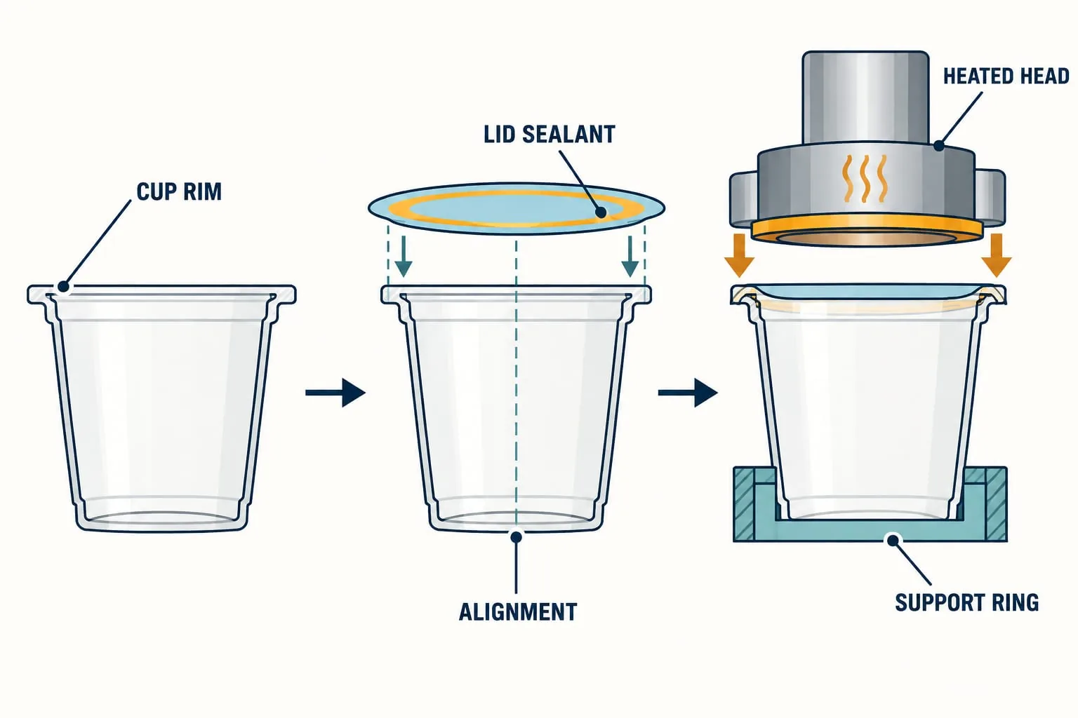
Record the cup material, outside rim diameter, rim shape and usable sealing land. Then identify the lid construction, sealant side and any printed or scored features that constrain orientation. If the line runs more than one format, record each format separately. A part that works on one rim profile may not distribute pressure correctly on another.
A simple cross-section sketch is valuable because it captures the interface rather than just the external machine body. Mark the cup rim, lid sealant, heated contact face, support ring and the intended centreline. The labelled guide above is a starting point for that record; the actual drawing should use measured details from the line.
Record the sealing head and support details
Photograph the head from above and below, with the machine isolated and the part cool. Note the head diameter or perimeter, mounting points, element route, terminal position, insulation or wear-strip arrangement, and how the support ring locates the cup. If the assembly uses replaceable sealing jaws and bars, record whether the heated face is integral, removable or backed by a separate element.
Also note the condition that caused the enquiry: open circuit, uneven seal, sticking, scorching, wrinkling, lid drift or a change after a format conversion. The symptom helps distinguish an electrical element problem from a mechanical alignment or material-interface problem.
Send measured evidence with the enquiry
A useful component enquiry includes the machine manufacturer and model, the cup format, the lid reference, clear photographs, the removed part’s dimensions and the reason for replacement. Include any drawing number, terminal detail, element resistance record or supplier reference that is already available. Measurements should be labelled with their datum and taken in a safe, isolated state.
If the assembly includes a replaceable wear layer, note its position and condition rather than treating it as raw material. PTFE heat-seal tape may be relevant to a particular sealing arrangement, but the correct grade, width, backing and installation method depend on the equipment and process. Ask for a compatibility review where the interface is not fully documented.
Common automatic cup sealing faults
Product or moisture in the seal area
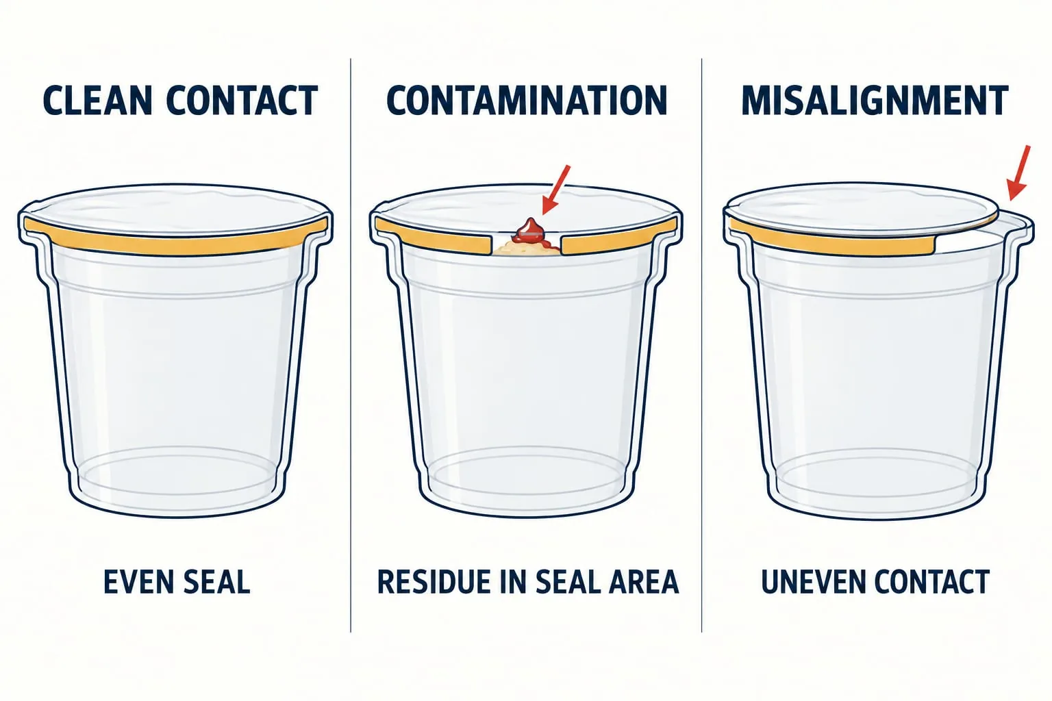
A clean rim is a basic requirement for a consistent seal. If product, condensate or cleaning residue reaches the contact land, it can interrupt the bond and create a leak path or visible channel. The Canadian Food Inspection Agency’s guidance on flexible-package sealing stresses that product should not contact the seal area and that filling, sealing conditions and material compatibility need to be controlled.
Check fill level, nozzle cut-off and splash behaviour before changing the heated component. Inspect the rim and lid path for residue, and confirm that the format parts keep the cup stable during transfer. A new element will not compensate for repeated contamination at the interface.
Uneven contact, misalignment or incomplete sealing
An uneven seal can come from a tilted cup, a damaged support, a head that is not parallel, a displaced lid or a sealing face that has worn locally. Incomplete sealing can also follow a change in dwell, pressure or temperature, but the mechanical checks should come first because they are visible and repeatable.
Compare the seal around the whole rim rather than judging one point. Look for a consistent contact band, a repeatable lid position and any mark that corresponds with a fastener, guide or damaged face. If the fault follows one pocket or one station, record that location; if it follows the lid roll or the product, widen the investigation beyond the head.
When to inspect the sealing surface
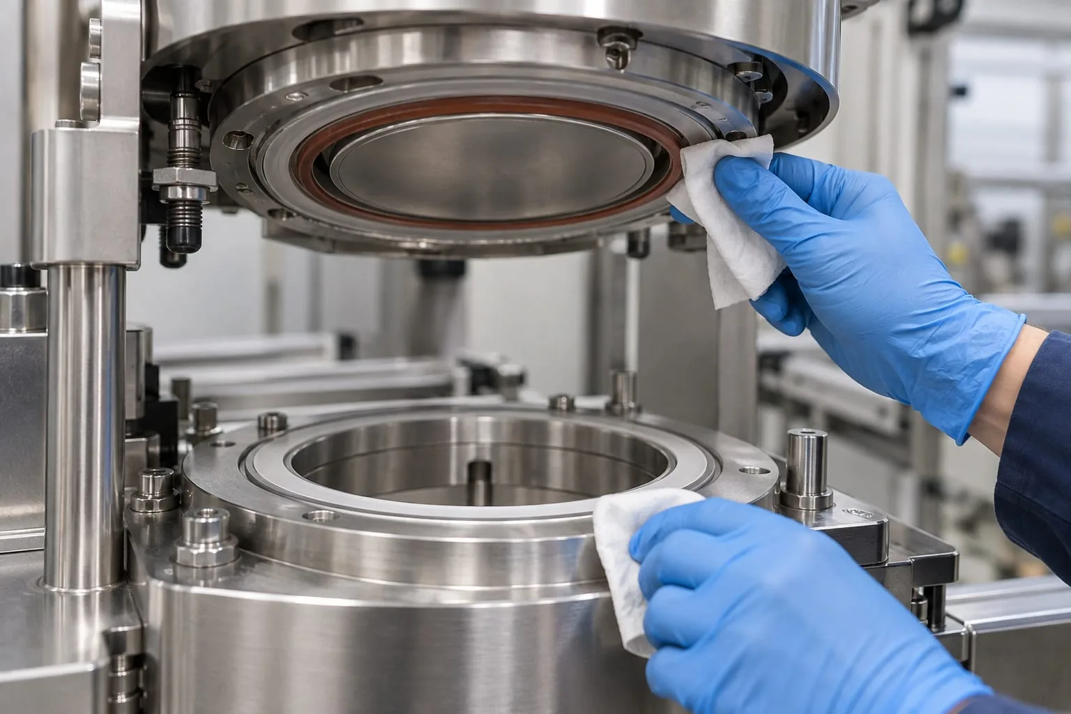
Inspect after a jam, format change, abnormal seal result, cleaning event or component replacement. Follow the site’s isolation procedure, wait for the assembly to cool and use the approved cleaning method. The aim is to find changes in flatness, contact marks, residue, loose fasteners, damaged insulation or a support that no longer seats correctly.
Use controlled samples and the site’s approved seal-integrity test after an adjustment. Do not release production on the basis of appearance alone. Keep the machine setting, material reference and test result together so that a later component change can be compared with a known condition.
Maintenance and controlled commissioning
Isolate, cool and clean before inspection
Use the manufacturer’s lockout, isolation and hygiene procedures before opening the sealing station. Let heated parts reach a safe condition, remove residue with the approved method and protect the seal face from scratches. A clean, undamaged interface is easier to measure and less likely to hide the original cause of a defect.
Do not introduce a solvent, abrasive or replacement tape simply because it is available. Confirm that the cleaning method and contact materials are suitable for the equipment, lid construction and site requirements. If a wear surface is damaged or lifting, document it and obtain the correct replacement instruction.
Validate after a component change
After fitting a replacement heating element or sealing face, check routing, terminals, insulation, fasteners and clearances before energising. Confirm that the head and support are parallel, the cup is stable and the lid is tracking through the intended path. Re-establish the approved process window rather than assuming the previous setting is transferable.
Run the site’s agreed test sequence with the intended cup, lid and product conditions. Record the material reference, setting changes, sample observations and acceptance result. If the defect remains, stop treating the element as the only suspect and return to the cup presentation, lid path, support and control sequence.
Keep a simple replacement record
A short record can prevent repeated guesswork. Keep the machine and format, part reference, dimensions, photographs, installation date, reason for change and post-change test result together. Add the supplier’s quotation or drawing when available, and note any differences between the removed and replacement parts.
This record becomes especially useful when several machines use similar cup formats but different heads or supports. It also gives a future enquiry enough context for a supplier to review the application instead of responding to a vague request for a generic heater. The Heat Seal Services overview provides a suitable starting point for related component enquiries.
What to send for a component review
A practical enquiry checklist
Before requesting a replacement or a custom component, assemble:
- machine manufacturer, model and station reference
- cup material, rim dimensions and supported formats
- lid or membrane reference and sealant-side information
- photographs of the head, support, terminals and installed position
- measured part dimensions, mounting details and any drawing number
- fault description, recent changes and the result of the last controlled test
- required delivery timing and whether the part is a like-for-like replacement or a revised design
Why application detail matters
The more clearly the interface is described, the easier it is to identify whether the enquiry concerns a heat-seal element, a sealing face, a support or a material-facing wear layer. Compatibility still needs to be confirmed against the actual machine and lid system; an article or catalogue page cannot certify a fit from the machine name alone.
Send the evidence in one pack and keep the original measurements so clarifying questions and post-change comparisons have a traceable basis.
Contact Heat Seal Components about the sealing assembly
Start with the interface, not just the machine name
If an automatic cup sealing station needs a replacement element, sealing face, support-related review or compatible PTFE-facing component, share the machine details, cup and lid references, photographs and measurements. Heat Seal Components can then assess the request against the component information available rather than guessing from a broad machine label. Contact Heat Seal Components with the enquiry pack and the required delivery context.