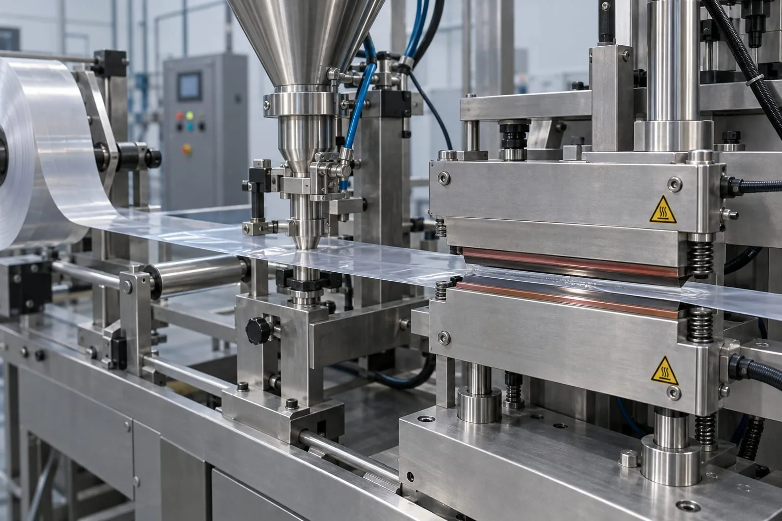
An automatic filling and sealing machine combines two jobs that must work together: placing the product accurately and creating a consistent heat seal around the film web. When the seal becomes weak, uneven or difficult to reproduce, the problem is often at the sealing interface rather than in the filling cycle alone.
This guide is for engineers, maintenance technicians and procurement teams specifying replacement parts for an existing line. Heat Seal Components supplies heat-seal elements, wires, endless bands, sealing jaws and bars, PTFE coating and PTFE heat-seal tape. It does not supply complete packaging machines, bags or films. For safe work on packaging machinery, follow the machine maker’s instructions and the relevant HSE packaging machinery guidance.
What the filling and sealing station actually needs
Separate the filling function from the sealing function
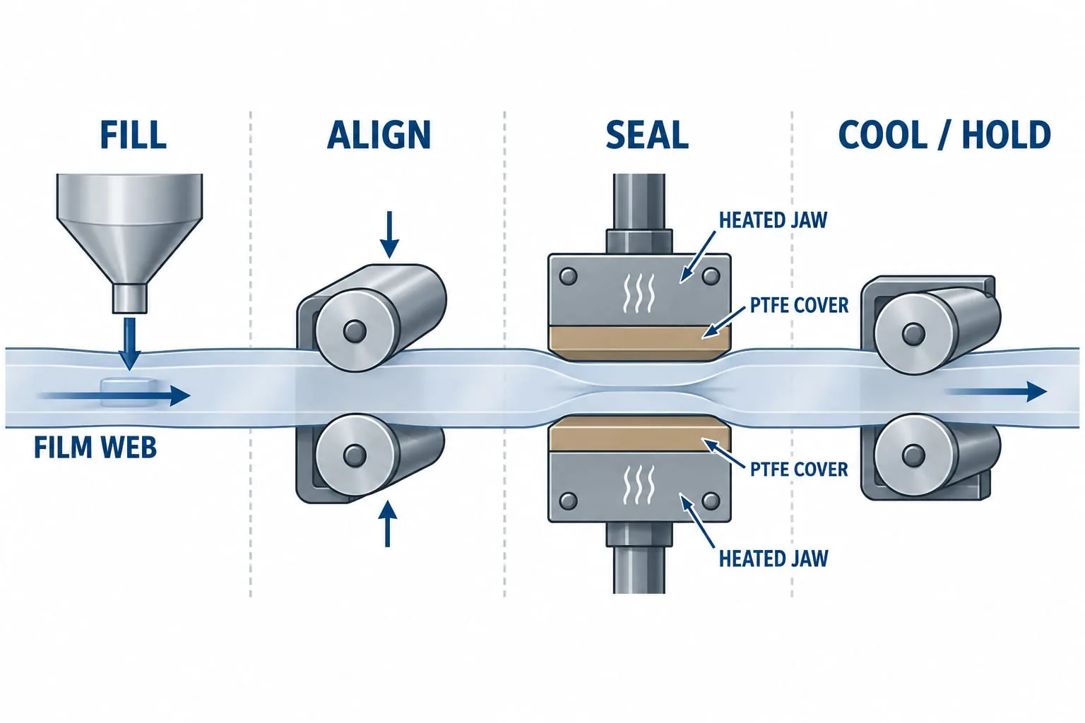
The filling system controls dose, timing and product position. The sealing station controls contact, heat transfer, pressure and the time available for the seal to form. A fault in one area can look like a fault in the other. Product in the seal zone may be caused by a filling or registration issue, while a clean but open seal may point to contact, temperature, dwell or component condition.
Start by identifying the exact station that is failing. Record whether it is a longitudinal or transverse seal, whether the jaws are heated, and whether the part is a complete jaw, a replaceable element, an element carrier, a sealing bar or a PTFE cover. This simple separation helps prevent ordering a visually similar part that cannot reproduce the original heat path.
The sealing interface is the part to specify
The interface is the short section where the two sides of the film meet under controlled heat and pressure. It may include a heated element or wire, insulation, a support bar, PTFE cover tape and terminals. Each item affects how evenly heat and pressure reach the film. The machine control-panel temperature is not, by itself, a specification for any one component.
Which components need matching
Heated elements, jaws and bars
A replacement element must match the machine’s physical arrangement and electrical requirements. Capture the installed length, width or diameter, fixing points, terminal position, insulation method and the way the element is tensioned or supported. If the element sits in a jaw or bar, record the full assembly and not only the visible heated section. See the heat-seal elements service and sealing jaws service for the relevant component categories.
Do not assume that a part with the same apparent length is interchangeable. A different terminal position, unsupported span or fixing detail can change the heat distribution and create a cold edge or a hot spot. Send a clear photograph beside a rule, plus a drawing or marked-up sketch where the profile is not obvious.
PTFE cover tape and support surfaces
PTFE cover tape helps protect the sealing interface and provides a controlled release surface. It must sit flat, without lifted edges, wrinkles, contamination or a damaged section across the contact zone. A cover that is too narrow may expose the element, while a cover that is applied unevenly can change the effective pressure across the seal.
Inspect the support surface beneath the tape as well. Burrs, adhesive residue and wear can hold one side of the jaw away from the film. Heat Seal Components also provides PTFE heat-seal tape and industrial PTFE coating when the existing release surface needs replacement or restoration.
Terminals, insulation and mounting
Check that the electrical connection is secure, insulated and routed away from moving or hot surfaces. Look for darkened terminals, loose fasteners, cracked insulation, exposed conductor and signs that the element has shifted. The correct replacement part must fit the mounting method without forcing the jaw or changing its alignment.
Check compatibility before ordering
Record machine and station details
The fastest route to a correct quotation is a complete identification pack. Include the machine maker and model, the station name, the seal orientation, the number of lanes or tracks, the part reference if available, and the material being sealed. Add photographs of the installed part, the removed part and the surrounding mounting points.
- Machine maker, model and serial or asset reference
- Seal position, orientation and approximate seal length
- Element or jaw dimensions in millimetres
- Terminal, fixing and insulation details
- Film structure, product type and observed fault
Measure the existing part in millimetres
Measure the part after isolation and cooling, using a clean rule or calliper. Record the overall length, active length, width, thickness or diameter, fixing-hole spacing, terminal centre distance and any bends or stepped profiles. Note whether the element is straight, formed, folded or tensioned. These details matter more than a generic description such as heating wire or sealing bar.
Confirm material path and seal pattern
Confirm how the film arrives at the jaws and where the seal is meant to sit. A horizontal seal, longitudinal seal, fin seal or edge seal can require a different jaw profile and support arrangement. Check whether the product can reach the seal area, whether the film is tracking centrally, and whether the seal pattern matches the drawing or validated sample.
Set up a controlled sealing process
Temperature, pressure and dwell time
Seal quality depends on the relationship between temperature, pressure and dwell time, as well as the sealant layer and material thickness. DuPont’s heat-sealing guidelines explain why the actual contact time and the conditions at the sealing face matter, not just the displayed machine setting. Change one variable at a time and record the result against a retained sample.
Avoid inventing a replacement temperature from the element material alone. Use the film supplier’s limits and the equipment maker’s validated range. If a new element changes the response of the station, recheck the actual seal result rather than assuming the old control setting remains correct.
Clean contact and alignment
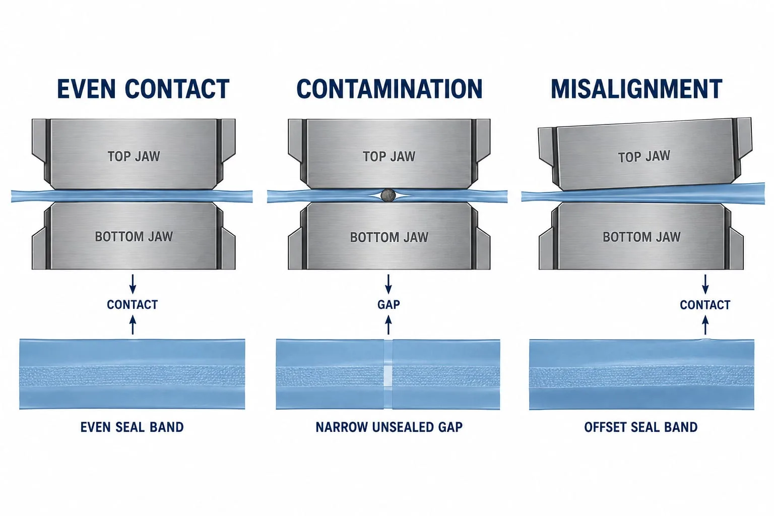
The sealing faces should close evenly across the working width. Remove residue using a method approved for the machine and material, then inspect the PTFE cover and the support surface. Check for a skewed jaw, uneven spring loading, a displaced element or a film path that is pulling the web to one side.
Use the machine manual and packaging supplier limits
The machine manual should define guarding, isolation, adjustment and test requirements. HSE guidance also expects work equipment to be maintained by competent people and inspected where deterioration could create risk. Keep the component drawing, test method and approved process range with the maintenance record.
Maintenance and fault finding
When a seal is uneven or incomplete
Begin with the simplest visual checks: contamination, a worn cover, an exposed or displaced element, a loose terminal, a damaged support face and jaw alignment. Then compare the defect with the machine cycle. A narrow unsealed line may indicate debris or a gap, while an offset seal band may point to skew or tracking. CFIA seal-defect guidance also recommends checking clean material, parallel surfaces, temperature, pressure and dwell, then validating with filled samples and an appropriate test.
If the fault appears after a component change, compare the old and new parts side by side. Check active length, fixing position, contact surface and insulation before adjusting the process. If the element is intact but the seal remains inconsistent, the jaw, cover, support or film path may need a closer engineering inspection.
Safe inspection and isolation
Heated jaws, elements and bars can remain hot after the cycle stops, and moving stations can close unexpectedly. Isolate the machine using the site procedure, prevent restart, allow the part to cool and verify the safe state before measuring or removing anything. Do not bypass guards or reach into a live sealing station. Follow the machine maker’s instructions and HSE work equipment FAQs for the applicable maintenance controls.
When a custom element or jaw is better
Non-standard shapes and legacy equipment
A custom component is worth considering when the original part has a formed profile, unusual terminals, a legacy mounting pattern or a non-standard active length. A direct replacement should preserve the intended heat path and fit. It should not be redesigned from a photograph alone if the drawing, material path or electrical information is missing.
Send photos and drawings for a quotation
For a quotation, send the machine and station identification, marked measurements, photographs of the installed and removed component, the seal fault and any available drawing or part number. Heat Seal Components can then assess whether a standard heat-seal element, sealing jaw, bar, endless band, PTFE cover or custom component is the appropriate route. The custom impulse heat-seal elements service is available for non-standard element requirements.
If you are unsure which part is responsible, send the complete interface rather than ordering a generic replacement. A clear component pack reduces delays, avoids avoidable rework and gives the replacement a better chance of matching the existing machine and validated process.