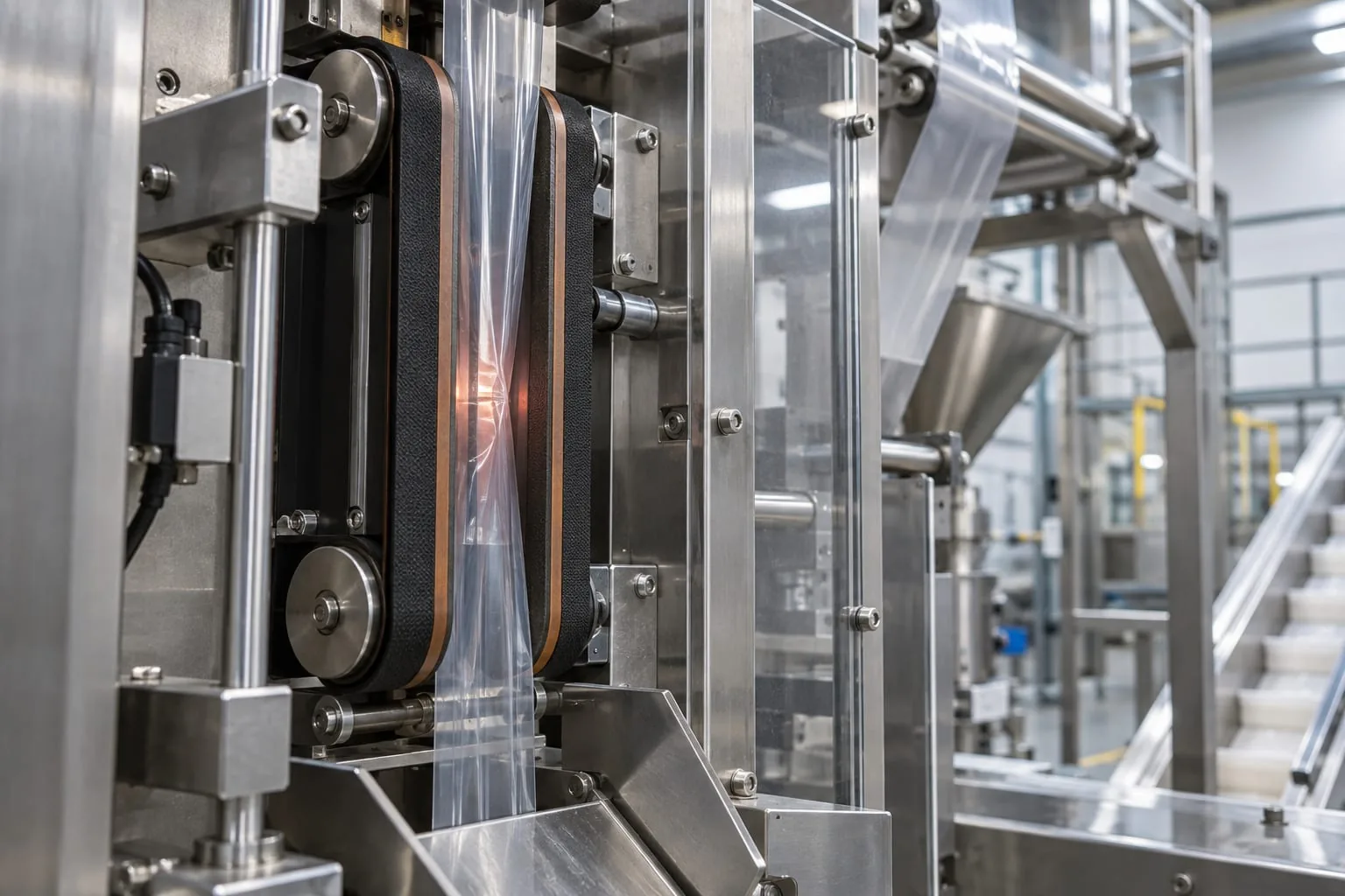
An automatic side sealing machine is an application, not a universal replacement-part specification. On a packaging line, film can travel through a side-seal assembly while other stations form, fill, cut or close the pack. The sealing components still have to match the machine geometry, film construction and operating method. This guide sets out the evidence to collect before ordering heat-seal elements, bands or related wear parts from a specialist supplier such as Heat Seal Components.
What the application does
Side sealing joins the longitudinal edge of a film web or formed pack. It is different from the cross seal that closes the top or bottom of a pack, although both operations may run on the same line. The side-seal assembly has to carry the film at a controlled speed while transferring enough heat and pressure to create a consistent seam.
Manufacturers describe side sealers as producing side-sealed bags from heat-sealable PE or PP film. Their working width, bag size, film thickness and cycle speed depend on the machine configuration. MACTEC’s side-sealer overview is useful background, but it is not a part drawing for another machine.
In a continuous system, the film passes through heated and cooled areas while moving bands or wheels carry it through the sealing path. TOSS’s explanation of continuous sealing also highlights the need for accurate adjustment, stable heat transfer and controlled speed. A machine name can identify the application. It cannot, by itself, identify the correct replacement band, heater or terminal arrangement.
The components that need matching
Start with the part that touches the film, then trace how it is heated, supported, driven and replaced. Heat Seal Components supplies heat-seal elements and related components for packaging applications, subject to the dimensions and evidence supplied for the specific machine.
Heated side-seal interface
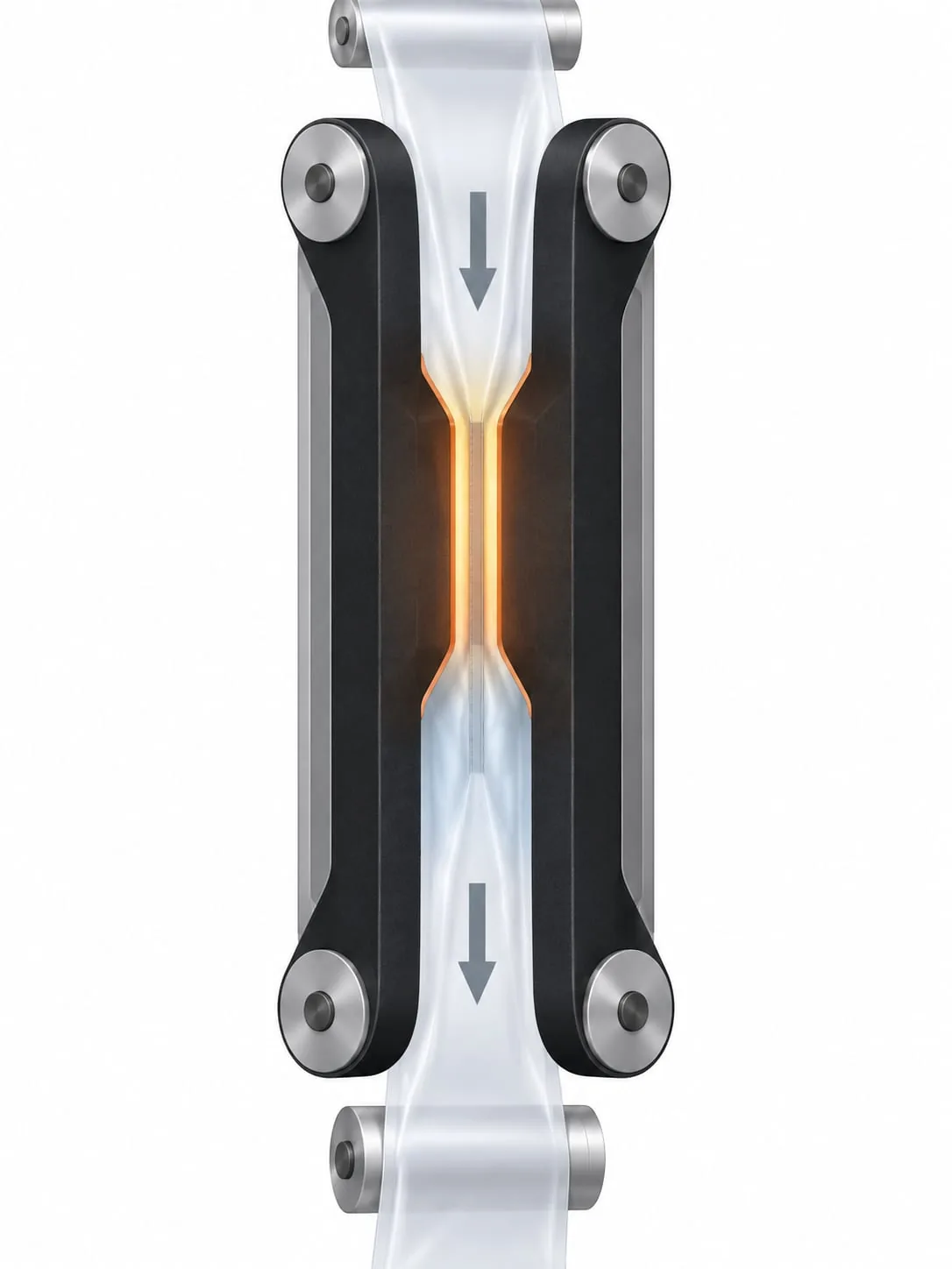
An automatic line may use an endless band pair, a fin-wheel arrangement or another continuous contact design. Do not assume that every side sealer uses the same format. Record whether the component is a band, wheel, heated strip or another assembly, then capture its route through the machine.
For a band system, note the band path, joint or endless construction, contact width, tracking method and any tensioning or guide features. Compare the old part with the machine drawing or a clear measurement record. A visually similar band can still be wrong if its length, surface, drive engagement or heat-transfer behaviour differs. See the heat-seal bands service for the relevant component category.
Cross-seal jaws, bars and covers
The side seam often works alongside cross-sealing jaws or bars that close and cut the pack. These parts may have a heater, pressure face, non-stick cover and cutting feature, depending on the equipment. Syntegon’s sealing and cutting guide describes the relationship between sealing jaws, heat, pressure, dwell and film. Treat the cross-seal assembly as a separate compatibility question even when it is controlled by the same machine.
If the enquiry concerns a jaw or bar, include the heated length, overall length, mounting pattern, terminal position, cover arrangement and any cut or serration profile. The sealing jaws and bars service can be used as a contextual reference, but the installed dimensions remain the controlling evidence.
PTFE covers and tape
Non-stick covers and PTFE heat-seal tape can protect a contact surface and help release the film. They are wear parts, so inspect for thinning, lifting, creasing, contamination or exposed metal before the line is returned to service.
Specify the application, width, length and backing or adhesive arrangement from the existing part or equipment documentation. A request for PTFE heat-seal tape should not be interpreted as a request for raw PTFE or plumbing tape. Those are different products with different uses.
Record compatibility before ordering
Build a short component record while the part is accessible and the machine identity is known. The record should include:
- Machine make, model and serial or line reference
- Seal orientation and path, including working width and any fin or jaw profile
- Film construction, thickness and product conditions at the seal
- Heated length, overall component length, terminal style and mounting details
- Photos of the installed part, adjacent supports, wear pattern and cable routing
Measure the installed path
Use the machine drawing where it is available, then confirm critical dimensions against the installed or removed component. Record what each measurement means. For example, distinguish heated length from overall length, and terminal centres from the outside length of the part. For a band, show the route and any guide or drive features rather than reporting width alone.
Photograph the component in place before removal if the orientation will be difficult to reconstruct. Include a ruler or another scale reference, but do not rely on a photograph for a dimension that can be measured directly. If a drawing and the physical part disagree, flag the difference for review instead of choosing the more convenient value.
Separate evidence from assumptions
A line may be described as automatic, continuous or side sealing while using a custom assembly. Mark each item in the record as measured, taken from a drawing, confirmed by the machine builder or still unknown. This prevents a familiar machine label from becoming an unsupported part number.
Why seal quality changes on an automatic line
A stable side seam depends on the relationship between the component, the film and the machine settings. The useful question is not only whether the seam looks bad, but where the process first departs from the approved condition.
Temperature, pressure, dwell and film
Sealing is a process window. Temperature, pressure and dwell time must suit the film construction and the actual contact arrangement. Syntegon’s technical material links reliable sealing with those variables and with film handling. If one variable changes, do not compensate by guessing at a different component.
Check the temperature feedback method, the condition of the heater or element and the pressure face. A new element will not correct a misaligned support, damaged cover or incorrect film path. Keep the approved machine settings with the component record so a replacement can be assessed against the same baseline.
Tracking and tension
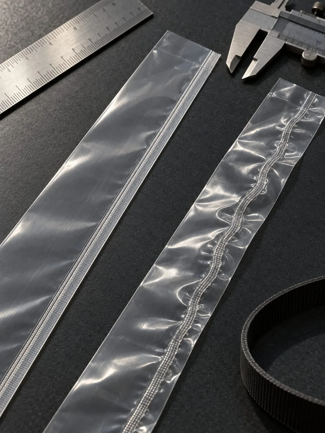
A moving side-seal band needs a stable route and even contact. TOSS notes that continuous systems rely on precise adjustment, film-synchronous drive and controlled heat transfer. If the seam wanders, inspect the band tracking, guide surfaces, film tension and frame alignment before changing the heater specification.
Look for a repeatable pattern. A seam that moves in the same direction through the run may point to tracking or tension. A local mark can point to contamination, a damaged surface or a contact problem. Record the film direction and the location of the defect on the sample.
Wear and contamination
Powder, product residue and adhesive transfer can change release and heat transfer. Worn covers, glazed bands and damaged contact faces can create a narrow defect even when the controller shows the expected temperature. Clean and inspect according to the machine maker’s procedure, then replace the worn wear part with a like-for-like, documented component.
Do not use a visual pass as the only acceptance test. Compare the seam with the approved sample and follow the site’s seal-strength or leak-test method where one exists.
Maintenance and safe component replacement
Before opening guarded areas
Plan the work around the equipment manufacturer’s procedure. HSE maintenance guidance advises isolating electrical and other energy sources, locking off where needed, releasing stored energy and allowing hot components to cool before work begins. Only trained and authorised people should carry out the task.
Keep the removed component, photographs and measurements together until the replacement has been checked. This makes it easier to spot a reversed orientation, missing support or incorrect terminal position before the line is restarted.
Inspect, replace and prove the result
After fitting, check the route, supports, covers, terminals, guards and clearances. Confirm that the band or film path is centred and that the component cannot contact an unintended surface. Reconnect and test under the site’s approved procedure, beginning with a controlled sample run.
Record the replacement date, part description, measured dimensions, film used, settings and test result. If the result is not repeatable, stop and investigate the process rather than repeatedly changing temperature or pressure.
What to send with a component enquiry
A useful enquiry gives the supplier enough evidence to check compatibility:
- Machine make, model and serial or line reference
- Clear photographs of the installed part and the surrounding assembly
- Measured dimensions, drawing extracts and terminal or mounting details
- Film construction, thickness and the sealing method used on the line
- The observed defect, when it appears and any recent component change
Heat Seal Components can help with heat-seal elements and wires, endless heat-seal bands, custom heating elements, PTFE coating and heat-seal tape, and sealing jaws or bars. This is component support for an existing packaging process. It is not a claim to supply a complete sealing machine, film or bags. For a practical review, send the available evidence to the Heat Seal Components contact team.
Choose the part from evidence, not the machine name
If you maintain a line described as an automatic side sealing machine, begin with the installed component and the film path. A clear photo, measured drawing and record of the operating condition will usually move the enquiry forward faster than the machine keyword alone. Use the evidence to confirm the contact surface, heater, support, drive and wear items as one compatible assembly.