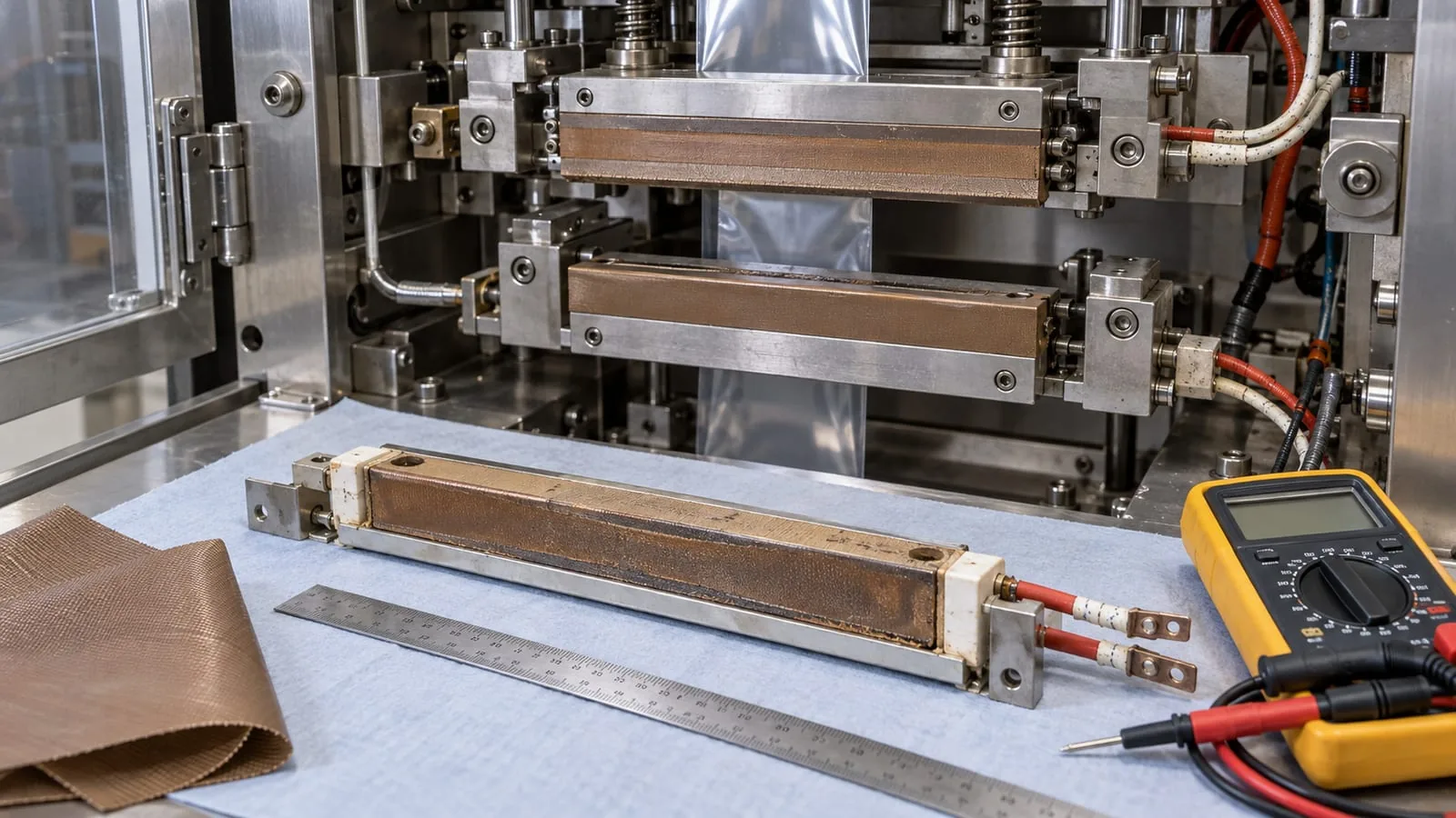
Heat-seal element failure is rarely just a case of fitting another strip and restarting the line. A loose terminal, incorrect resistance, uneven support, damaged PTFE cover, contamination or unstable temperature control can all create a weak seal or a repeat failure.
The useful question is not only “why did the element break?” It is “what changed the electrical, thermal or mechanical conditions around it?” This guide gives maintenance and procurement teams a structured first inspection, while keeping replacement selection tied to the actual machine application.
Start with safe isolation and a visual check
Before opening a sealing jaw or removing an element, follow the machine maker’s isolation procedure and site permit controls. The HSE packaging machinery guidance highlights the risks around guarding, cleaning and maintenance on packaging equipment. Do not treat a cool-looking jaw as proof that stored energy, movement or electrical risk has been removed.
Look at the element, support and cover
With the equipment safe to inspect, photograph the installed arrangement before disturbing it. Look for a break, necking, scoring, darkened areas, lifted edges or a section that no longer sits evenly in its support. Check whether the element is a flat ribbon, round wire, shaped wire or a formed component, and note how its ends are retained.
The support should hold the element consistently along its active length. A displaced support can change the way heat leaves the element, while a damaged or contaminated cover can change the contact surface. Do not assume the visible break is the original cause. It may be the final symptom of a problem that began at a terminal or mounting point.
Check the terminals and connections
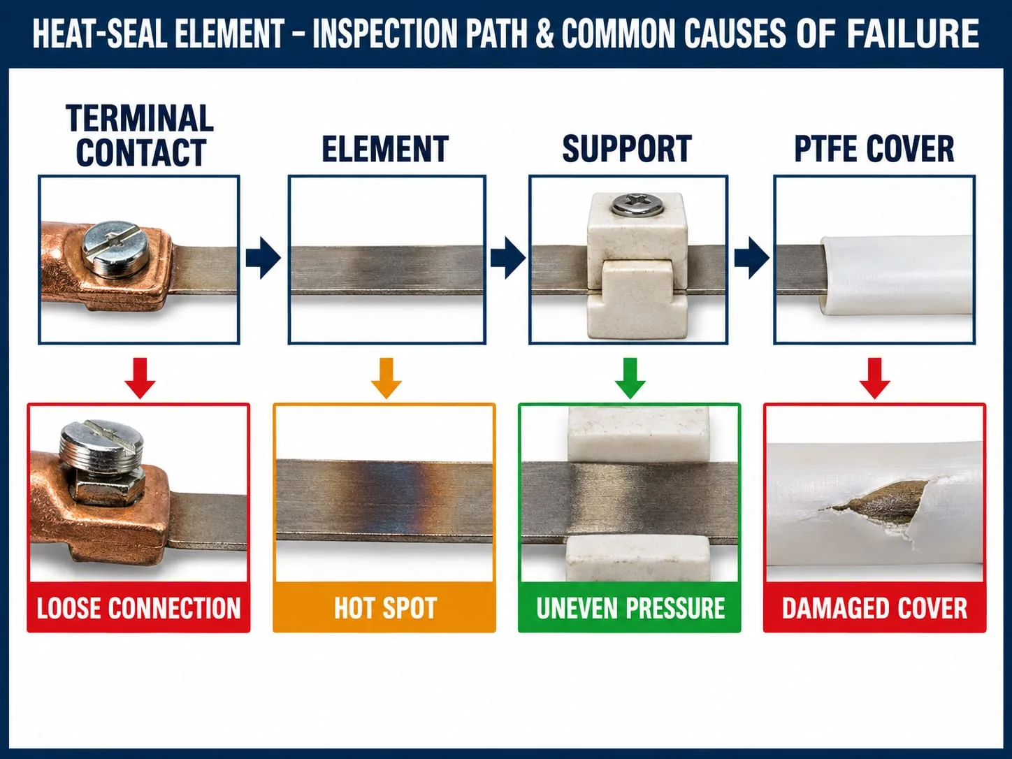
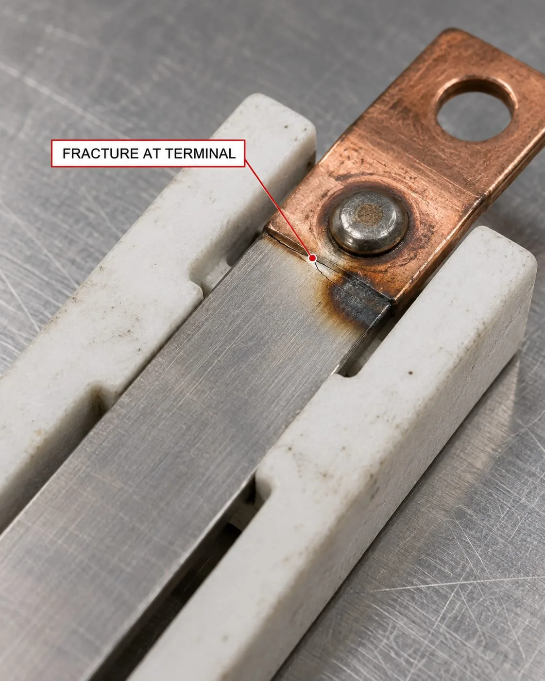
Inspect both ends for looseness, movement, discolouration, oxide, pitting, crushed fasteners or a change in the clamping arrangement. A poor connection can create local heating at the joint instead of distributing heat through the intended element. A crack close to a terminal can also point to mechanical strain or repeated thermal cycling.
Record the terminal shape and orientation as well as the element length. A visually similar replacement can still be wrong if the terminal arrangement, active length or support path differs. Heat Seal Components supplies heat-seal elements and can review the component details before a replacement is specified.
Common causes of heat-seal element failure
The inspection path below separates the four areas most likely to change the element’s working conditions. It is a starting point for diagnosis, not a substitute for the machine manufacturer’s service procedure.
Overheating and unstable temperature control
An element may be exposed to more thermal stress than intended when a controller, sensor, relay, wiring path or cooling arrangement is not behaving correctly. Repeated rapid temperature changes can also shorten element life. Kanthal’s design-calculation guidance explains why element temperature, surface load, heat dissipation and wire dimensions matter together.
Check the temperature-control history and the condition of the sensor and wiring before blaming the replacement element. If the same failure returns quickly, compare the operating conditions at the time of failure with the machine’s documented settings. Do not increase or reduce settings simply to make a new element last longer without the equipment maker’s approval.
Poor contact or incorrect resistance
The connection between the supply path and the element needs to be clean, secure and mechanically stable. A poor joint may create a hot spot at the terminal, while a replacement with the wrong resistance can change the electrical load on the control system. There is no universal resistance value that is safe for every sealer.
Measure and record the failed part only when the site procedure and test equipment make that safe. Compare the result with the original specification or a known-good component, not a generic online value. For a non-standard shape or application, custom impulse heat-seal elements may be a better route than adapting a visually similar part.
Contamination, moisture and corrosive residue
Product residue, cleaning chemicals, moisture, dust and handling contamination can affect terminals, covers and the element surface. The Kanthal resistance-wire guidance lists contamination, atmosphere, surface condition and mechanical stress among the factors that influence element life.
Inspect the whole heat path rather than wiping only the visible break. Look at the terminal hardware, support material, cover and nearby surfaces. Use only the cleaning method approved for the equipment and component materials. If a cover is worn or no longer protects the element correctly, replacing the element alone may leave the underlying failure condition in place.
Support, alignment and PTFE cover problems
An element needs the correct mechanical path as well as the correct electrical connection. A support that has shifted, cracked or compressed can leave part of the ribbon unsupported. That can create local movement, an uneven heat path or repeated flexing at the same point.
The cover is part of the working interface. A torn, folded or contaminated PTFE cover can expose the element, alter release behaviour and transfer residue into the sealing area. Heat Seal Components can supply PTFE heat-seal tape and PTFE coating within the confirmed component range. The correct choice still depends on the machine design and the existing assembly.
Check alignment with the jaw open and closed only under the site’s approved procedure. Look for witness marks, uneven contact, fasteners that have moved and a cover edge that is being pinched. If the jaw or bar itself is damaged, record that separately. Sealing jaws and bars are a component category, not proof that an element is the only failed part.
Separate the element fault from the machine fault
Replacing the failed part is not the same as proving the fault has been cleared. When the machine is safe to test, confirm that the element sits correctly, the terminals are secure, the cover is correctly applied and the surrounding jaw or bar returns to its intended position. Follow the equipment maker’s commissioning and test procedure.
Check the surrounding components
Use the failure pattern to decide what evidence to collect:
- A clean break in the active length may call for a closer look at overheating, cycling, tension or the element’s working conditions.
- Darkening or pitting at a terminal points attention towards contact pressure, joint condition, contamination and cable termination.
- Repeated failure at the same support or cover edge points towards alignment, movement or an uneven mechanical path.
- A new element that does not heat or seal as expected should trigger a compatibility check rather than an immediate setting change.
- Keep the failed component. Its profile, terminal arrangement and damage pattern can be more useful than a description written after disposal.
A practical replacement and ordering checklist
Before requesting a replacement, collect the information that distinguishes one component from another:
- machine type and application, such as a vacuum packer, impulse sealer, VFFS or flow-wrap line;
- element form, material information if known, active length, overall length and width or diameter;
- terminal type, terminal spacing, orientation and fixing method;
- support, cover and jaw or bar arrangement, including any damage or recent changes;
- the original part reference, photographs before removal and the reason for failure;
- any safe, verified resistance or temperature information from the machine documentation.
This record helps procurement avoid ordering a generic part that fits the envelope but not the electrical or mechanical design. Heat Seal Components also supplies heating elements for compatible applications. If you are unsure which details matter, contact Heat Seal Components with clear photographs and the component measurements.
The aim is a controlled replacement decision: identify the failure condition, check the surrounding assembly, and match the new component to the actual machine application. That approach is more useful than treating every broken element as the same problem.