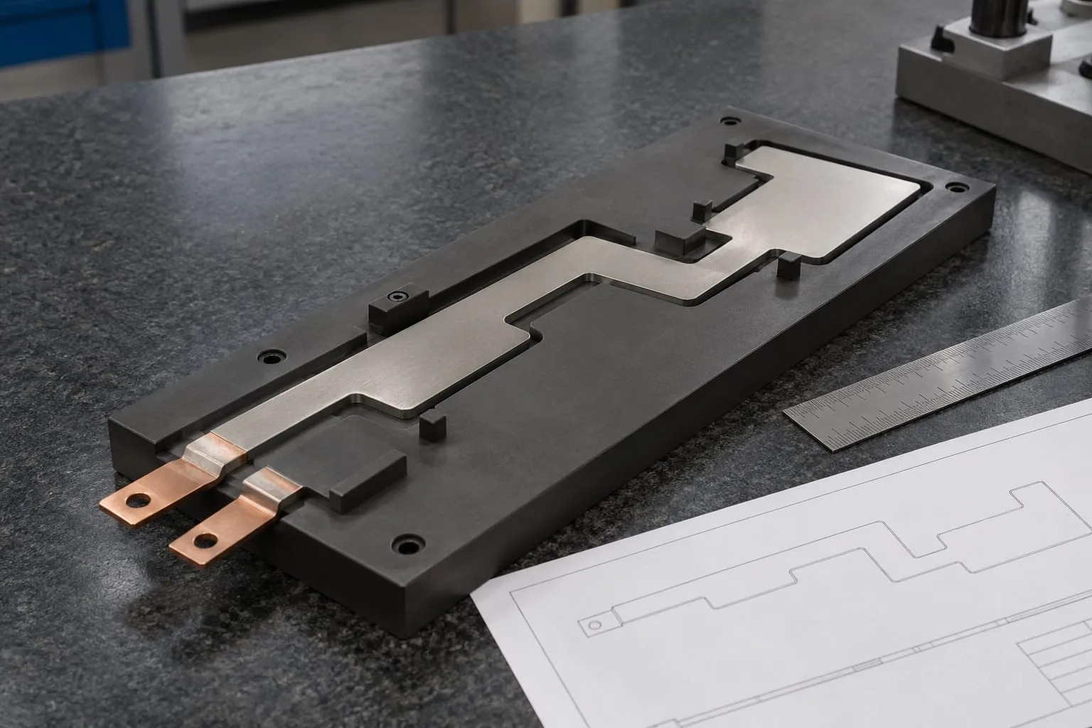
Replacing a heating element is easier when the replacement request contains enough evidence to identify the part. A photograph alone may show the general shape but not the active length, terminal arrangement, support details or electrical data that affect fit and operation.
This checklist helps maintenance and procurement teams prepare a clear request for a custom element. It applies to sealing equipment where the element works with a jaw, bar, band or other sealing assembly. It is a specification aid, not a substitute for the machine maker’s instructions or a competent electrical assessment.
What a custom heating element specification should capture
A useful specification joins the element’s physical form to the way it is installed and used. The request should give the supplier enough information to distinguish the active heating part from its terminals, support, cover and neighbouring components.
Start with the element type and profile
State whether the existing part is a round wire, flat ribbon or custom profile element. Note any steps, bends, holes, slots, cut-outs or changes in width. A simple description such as “flat element” may still leave several possible profiles.
Heat Seal Components describes custom impulse elements as parts that can be produced to a supplied specification. That makes the quality of the specification important: the outline, connection details and application evidence should be recorded together.
Separate active dimensions from mounting dimensions
Measure the length and width of the heated section separately from the overall part. Also record the distance between terminals, fixing points, holes, slots and any clearance features. Mark which dimensions are taken from the element itself and which are taken from the jaw or bar.
Do not assume that an overall length is the same as the active sealing length. A terminal, cold end or supported section may sit outside the heated zone. If a drawing is available, label each dimension and include its unit, tolerance if known and measurement method.
The specification checklist
Use the following fields when preparing a request. If a value is not known, write “to be confirmed” and attach the evidence that may help resolve it. A stated unknown is safer than a guessed value.
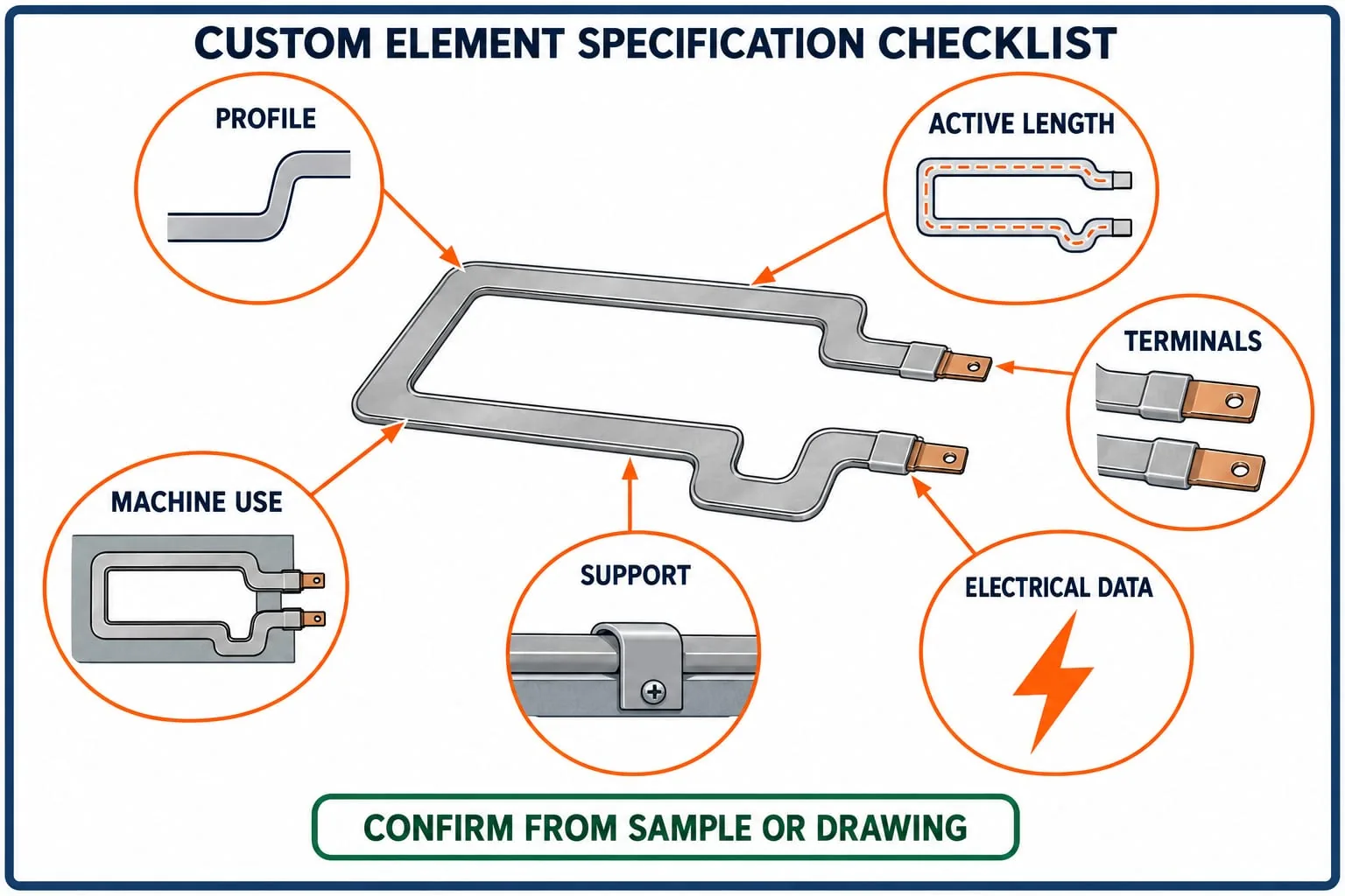
Profile: round wire, flat ribbon or custom outline, with a sketch or marked photograph. This helps identify the physical part and any non-standard features.
Active dimensions: heated length, width or diameter, bends, steps and clearances. This separates the sealing zone from terminals and supported areas.
Terminals: position, shape, hole or slot detail, orientation and any plating visible on the sample. This supports correct connection and physical fit.
Support and cover: ceramic, PTFE-coated or other adjoining parts, including order of assembly. This helps prevent a correct element being fitted into the wrong stack-up.
Electrical data: voltage, wattage, resistance or machine record, with its source and condition. This prevents values being inferred from appearance alone.
Machine use: machine type, sealing station, film or pack format where relevant, and part location. This links the component to the actual application and compatibility check.
Match the element to the sealing assembly
The element is only one part of the sealing station. The replacement must be considered with the parts that hold, insulate, cover and press it. Heat Seal Components also supplies sealing jaws and bars as part of its component range, so the request should identify the related assembly rather than describe the element in isolation.
Record the machine and sealing station
Record the equipment type and the location of the part: for example, an impulse sealing jaw, a vacuum-pack sealing bar, a vertical form-fill-seal station or a flow-wrap sealing assembly. Include the machine make and model only as identification evidence. Do not assume that a part is compatible solely because two machines have similar names.
Add the sealing width, orientation and whether the element is used against a matching jaw, band or coated surface. Where the part is removed for inspection, photograph it in position before dismantling so the original orientation is not lost.
Check support, cover and adjoining parts
Record the support material, insulation, retaining method and any cover or release layer. If PTFE heat-seal tape or another coating sits over the element, state whether it is part of the replacement request or a separate maintenance item.
Look for compression marks, uneven contact, scorching or movement in the support. These observations do not prove the cause of a seal defect, but they can identify evidence that should be reviewed before ordering a new component.
Electrical details need evidence
Resistance-heating parts convert electrical energy into heat, but the correct value depends on the element design and the equipment circuit. A similar-looking part is not proof of the same electrical specification.
Record what is known, not what is guessed
Copy voltage, wattage, resistance or controller information from the machine plate, service record, drawing or a competent test record. State whether the reading was taken cold, after removal or under another known condition. If the element is damaged, record the limitation instead of estimating a value from a partial measurement.
The Kanthal resistance-alloy handbook explains why resistance and resistivity need technical context, including the effect of temperature. Use that background to avoid treating a single unqualified reading as a complete design specification.
Treat terminals as part of the design
Terminal shape, spacing, orientation and plating can affect both connection and fit. Photograph each end with a scale and mark the terminal positions on the drawing. If the terminal is bent, burnt or loose, note that condition and provide a second photograph before attempting to straighten it.
For impulse applications, compare the request with the available custom impulse heat-seal elements information. The application and the physical evidence still need to be checked together before a replacement is specified.
Use a sample, drawing and photos
The strongest request usually combines a removed sample with a marked drawing and photographs taken before and after removal. Each source answers a different question: the sample shows the physical part, the drawing records dimensions, and the photographs preserve orientation and surrounding assembly details.
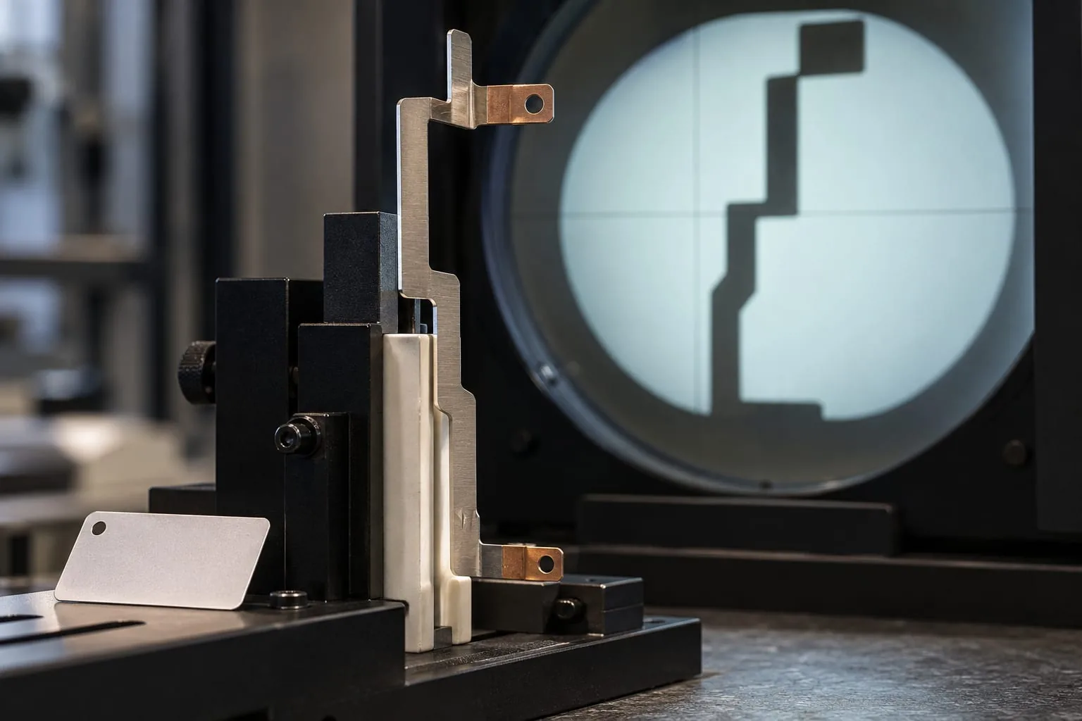
Minimum evidence pack
- A clean photograph of the complete element beside a millimetre scale.
- Close views of both terminals, bends, holes, slots and damaged areas.
- A marked drawing showing active length, overall length, width, profile changes and terminal centres.
- The equipment make, model, sealing station and position of the part.
- The machine plate, service record or other source for electrical information.
- Notes on the support, cover, insulation and any heat seal elements already fitted nearby.
Keep the original files and label each view. A cropped image can hide a terminal offset or a support feature that matters to compatibility.
When the sample is damaged
If the element is open-circuit, distorted or partly missing, send the remaining piece and explain what is missing. Add measurements from the jaw or bar, the original installation photographs and any previous order or drawing. The goal is to identify uncertainty clearly so it can be resolved before manufacture.
Safe inspection and review
Inspection should be planned around the equipment’s risks. HSE maintenance guidance recommends suitable maintenance arrangements, competent people and following manufacturer instructions. Before touching a heated or electrically connected sealing assembly, isolate it, prevent unexpected start-up and allow hot parts to cool.
Isolate, cool and record
Confirm the equipment is isolated under the site’s procedure. Use suitable access and lighting, and keep hands and tools clear of stored energy or moving parts. If an electrical test is required, use a competent person and appropriate equipment. HSE’s GS38 guidance is a useful reference for low-voltage electrical test practice, but site procedures and the machine manufacturer’s instructions remain essential.
Take photographs before cleaning or straightening anything. Record the condition of the element, support, cover and terminals as found. This keeps the specification tied to the original evidence and avoids turning a damaged part into an undocumented “standard” shape.
How to send the request for a quote
Send the checklist, marked drawing, photographs and equipment details together. Identify which values are measured, which come from the machine record and which still need confirmation. If you need help assembling the component information, contact Heat Seal Components with the sample or drawing available. The team can review the request against its component range and confirm what further information is needed.