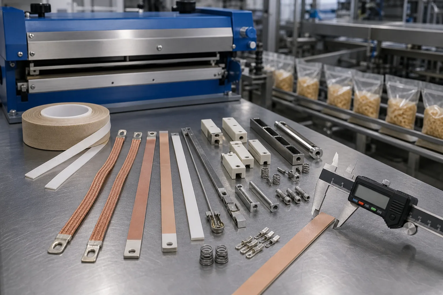
Measure the replacement element’s width and confirm its profile, terminals, and mounting hardware before ordering.
Heat seal elements and wires are replacement heating components used to create controlled heat across impulse sealers, vacuum packers and packaging machinery. Selection depends on the machine, element profile, heated length, dimensions, mounting and electrical specification, so submit accurate measurements and machine details before ordering. Heat Seal Co supplies heat seal elements, seal wires and custom impulse components for compatible packaging equipment, with product-page enquiries available for specification review and quotation.
A failed heat seal element or worn seal wire can cause poor seals, scorching, downtime and uneven pack quality. These parts are used in wire sealing machines, bench sealers, vacuum packers, VFFS lines and flow-wrap systems. When choosing a replacement, check the exact size and design. Do not rely on the machine name alone.
This guide explains how heat-seal wires, ribbons and custom impulse parts work. It shows you how to measure them safely and what details to check before ordering. It also covers common faults, resistance and continuity tests, PTFE cover tape, sealing jaws and bars, and installation checks. You will also learn what information to provide when a standard replacement is not suitable.
First, identify the sealing process. Then record the original part’s heated length, overall length, width, thickness, fixing positions and connection type. Next, review the relevant Heat Seal Elements & Wires options. You can also send your machine details, measurements and photographs through the Heat Seal Co product pages for a compatibility review and quotation.
What Are Heat Seal Elements and Wires?
How the component works
A heat seal joins compatible thermoplastic materials. It uses heat, pressure and contact time. Heat softens the sealable material. Pressure and cooling then create the bond.
A heat seal element is the part that heats up. It transfers heat to the packaging material. It may be a round wire, flat ribbon, shaped part or continuous band. The type used depends on the sealing assembly.
- Temperature: the component must reach the required sealing temperature.
- Pressure: jaws, bars or support surfaces must apply even force.
- Dwell time: the material must stay in contact long enough to form the seal.
If one setting is wrong, the seal may be incomplete. The material may also scorch, stick or suffer local damage. Replacing the heated component may not fix the problem. Pressure, cover tape or electrical control may also need attention.
Wire, ribbon, shaped parts and bands
Round heat-sealing wire creates a narrow seal line. Flat ribbon creates a wider sealing area. Shaped parts may have bends, holes, terminals or profiles. These features are made to fit a specific jaw. Endless bands are used in compatible continuous assemblies.
The profile, heated length, resistance, terminals, tension and mounting method must match the original part. Do not choose a replacement by length alone. PTFE cover tape can protect the active surface. It can also stop packaging material from sticking. Worn tape may affect heat transfer and service life.
| Arrangement | Possible component | Primary checks |
|---|---|---|
| Impulse or bench | Wire, ribbon or formed part | Heated length, profile, terminals, tension and cover |
| Vacuum packing | Bar-mounted wire, ribbon or formed part | Jaw dimensions, fixing points, resistance and cover |
| VFFS or flow-wrap | Continuous band or formed component | Band dimensions, tracking, tension and machine interface |
| Industrial bag sealing | Wire, ribbon, band or paired parts | Duty cycle, pressure, connections and electrical specification |
For replacement Heat Seal Elements & Wires, provide the machine details, measurements and photographs. This allows compatibility to be checked before manufacture or supply.
Which Replacement Component Does Your Machine Need?
Impulse and bench equipment
An impulse or bench unit may use a straight wire, ribbon or formed part on a sealing jaw. Check the sealing length and heated length. Also check the profile, resistance, terminals and mounting method. A part may fit the jaw but still heat incorrectly if its shape or electrical details are different.
Cut-and-seal jaws may need a profiled or combined component. Unusual apertures, bends or fixing points may need a custom impulse part. Before ordering, compare the original part with a drawing or verified sample.
Industrial and heavy-duty applications
An industrial bag sealer or heavy-duty heat sealer may use a long wire, ribbon, endless band or several components. Check the complete assembly. Do not choose a replacement only because it looks stronger.
- Jaw or bar length and usable heated length.
- Wire or ribbon width, thickness, profile and known material specification.
- Terminal type, hole size and fixing centres.
- Spring, clamp or other tensioning arrangement.
- PTFE cover, insulation, backing and support condition.
- Whether one, two or several components work together.
A change in component size alters resistance and heating. It may also affect the controller settings. For obsolete or modified equipment, provide photos, dimensions and machine details for review.
Vacuum, VFFS and flow-wrap equipment
Vacuum packers often use bar-mounted parts with set terminals and fixing points. VFFS and flow-wrap machines may use continuous bands or formed parts. These parts can be used in longitudinal, transverse, fin or lap sealing stations. Identify the station, sealing pattern, component path, dimensions, tension and connections.
Machine names and model references can help identify a compatible part. However, they do not confirm the correct replacement. Differences may result from the machine’s age, production changes, jaw modifications or earlier repairs. Send the machine specification and component details for a quotation.
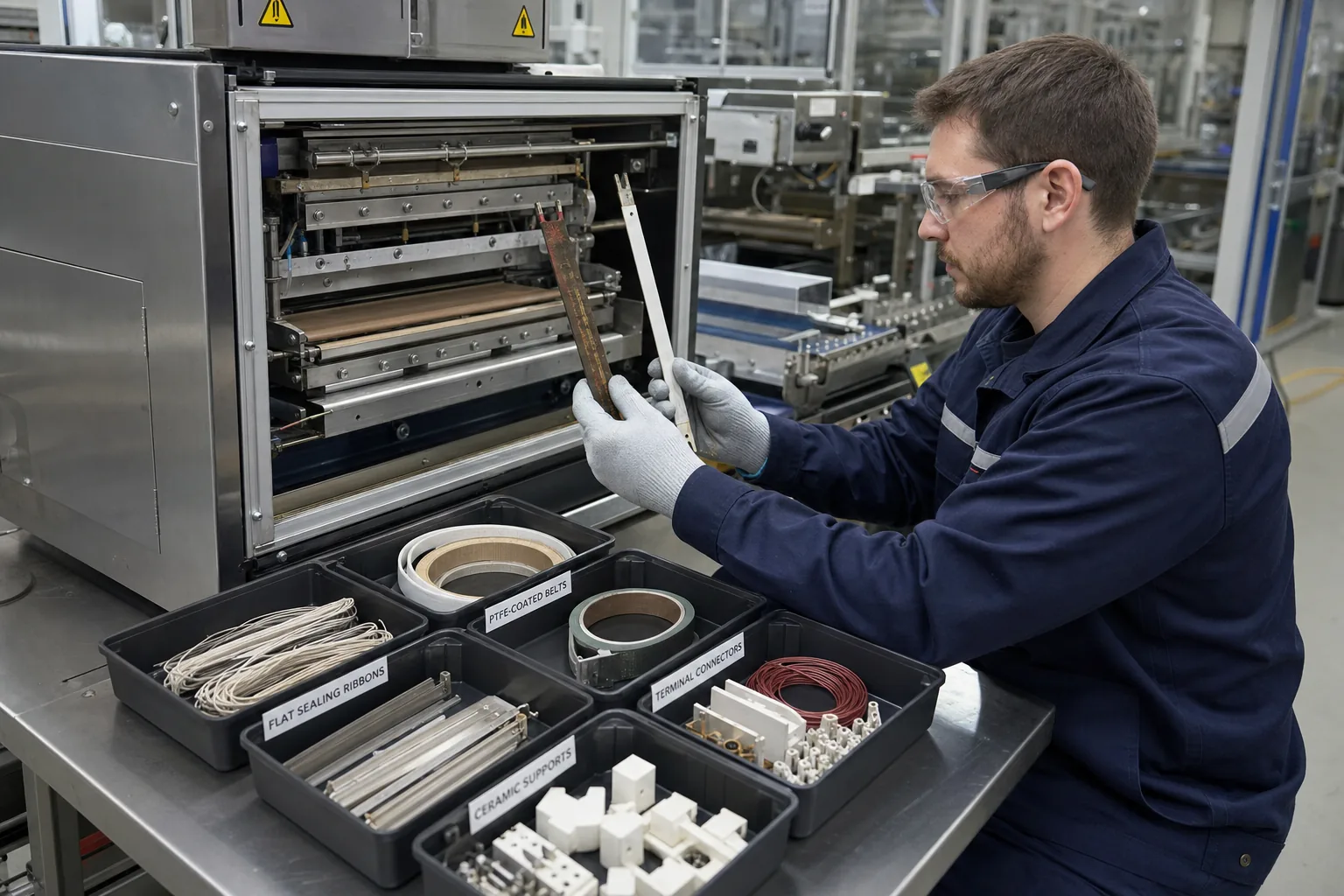
Identify the failed component before ordering a replacement. Heating wires, sealing ribbons, PTFE belts, connectors, and ceramic supports require different specifications and may not be interchangeable.
How to Specify a Replacement Component
Measurements to record
Measure the original part while it is relaxed. Do not stretch, flatten or straighten it. Record all sizes in millimetres. Also, note the difference between the total length and the heated length.
| Measurement | Record | Purpose |
|---|---|---|
| Overall length | End-to-end length, including formed ends | Checks the physical fit |
| Heated length | Active section between the terminals or inactive ends | Checks seal coverage and resistance |
| Width and thickness | Wire diameter or ribbon size | Identifies the profile and electrical behaviour |
| Terminal position | Distance from a fixed reference point | Checks connection alignment |
| Fixing position | Holes, slots, hooks and centre spacing | Checks the mechanical fit |
For bends, notches or shaped ends, make a dimensioned sketch. Mark each feature from a fixed reference point. If the original part is broken or stretched, also measure the jaw, support and retaining points.
Connection and machine information
Record the terminal type and the hole or slot sizes. Also note the spring or clamp arrangement, insulation, cover tape and element orientation.
Provide the manufacturer, model and serial number, if available. Include the sealing station, jaw or bar position, application and sealing material. Add any known voltage, power or resistance details.
Terms such as commercial bag sealing machine, industrial impulse sealer and heavy duty sealing machine do not provide enough detail. Include clear photos of the complete assembly, both ends, terminals and support surfaces.
For non-standard parts, send a sample or a dimensioned drawing. This will help us prepare a custom quotation.
How to Measure the Component Safely
Length and profile
Isolate the equipment and allow it to cool before inspection. Measure the overall length, heated length, end allowances, wire diameter or ribbon width and thickness. Do not straighten a shaped part to obtain one measurement; record each leg, bend, hole and terminal position.
Use callipers where practical and take photographs with a scale. Measure the jaw or bar as an additional reference if the original is broken, distorted or unavailable.
Terminals and supports
Measure hole diameter, slot dimensions, centre-to-centre spacing, terminal distance from the heated zone, fixing span and the position of springs, clamps, insulating washers and support strips. Photograph the component in position before removal.
Inspection procedure
- Apply the site isolation procedure.
- Photograph the installed part and connections.
- Remove loose residue without bending the part.
- Measure the component on a supported surface.
- Record breaks, discolouration, stretching and damaged terminals.
- Inspect PTFE cover tape, insulation and the supporting jaw.
Do not alter the part to make measurement easier. If dimensions are uncertain, submit the sample, photographs and jaw details for review.
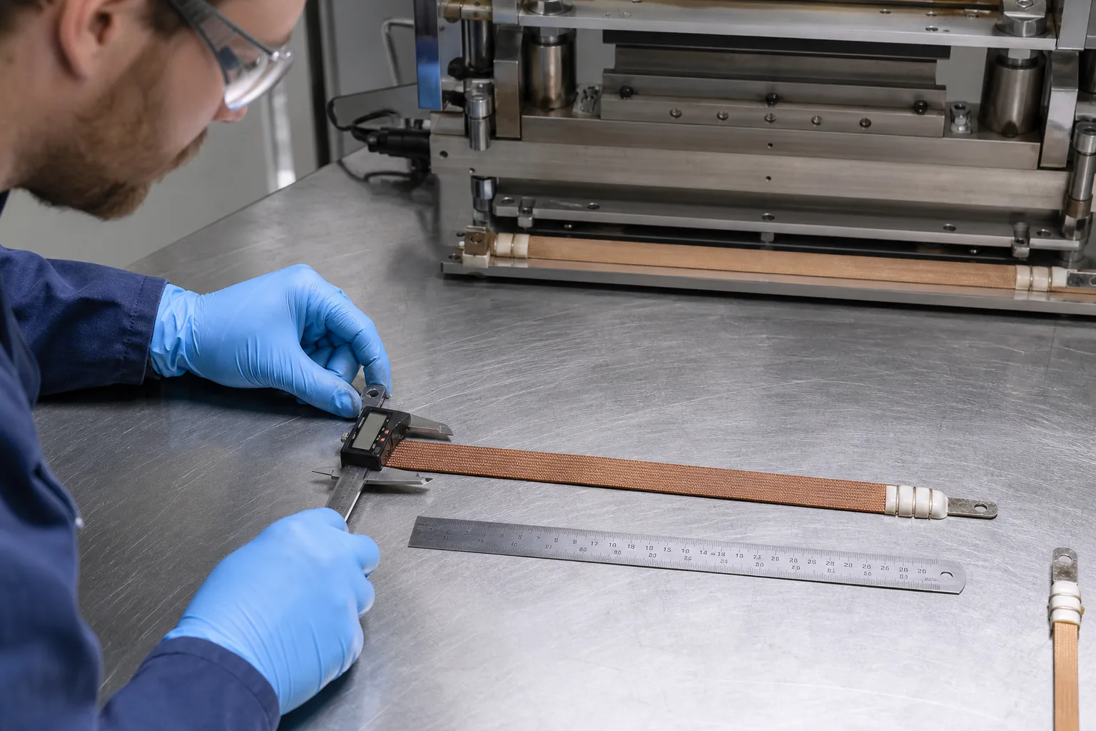
Measure the removed element while the sealer is disconnected and cool. Record its length, width, thickness, terminal spacing, mounting holes, and other dimensions needed to match the replacement.
How to Choose Heat-Sealing Wire or Ribbon
Resistance wire selection
Heat-sealing wire is a resistance-alloy component designed to generate heat when current passes through it. Material, cross-sectional area and heated length determine resistance. The machine’s supply and control system determine whether that resistance is suitable.
Terms such as “nichrome wire” do not identify a complete replacement specification. Confirm diameter or ribbon dimensions, heated length, resistance, terminals, profile and mounting method. A different diameter or length can change current demand and heat distribution.
Wire versus ribbon
| Feature | Round wire | Flat ribbon |
|---|---|---|
| Contact profile | Narrow line | Wider surface |
| Key dimensions | Diameter, heated length and end form | Width, thickness, orientation and length |
| Main risks | Incorrect tension or diameter | Incorrect orientation, width or thickness |
Do not substitute ribbon for wire, or wire for ribbon, without checking the jaw, cover system and electrical circuit. Physical fit does not prove compatibility.
Selection checklist
- Machine manufacturer and model.
- Wire, ribbon, formed part or band profile.
- Overall and heated length.
- Diameter, width and thickness.
- Resistance and test conditions, if available.
- Terminal and fixing details.
- Photographs and application information.
Submit the complete specification for a compatibility review before ordering.
What Other Component Features Matter?
Electrical resistance and material
The component material, cross-section and heated length affect resistance, heating response and service life. Measure resistance only with the component isolated from the circuit, and compare it with an approved reference or machine documentation. A resistance reading does not identify every material or prove that the part is suitable.
PTFE cover tape
PTFE cover tape separates the heated surface from the packaging material and supports release. Check its width, thickness, condition and position. Replace tape that is cut, thin, blistered, contaminated, wrinkled or exposing the active component. The correct cover arrangement depends on the sealing jaw and profile.
Jaws, bars and supports
The heated component works as part of a complete assembly. Inspect jaw faces, pressure pads, supporting strips, fasteners, alignment and contamination. A new part may not correct poor sealing if the bar or support is worn or distorted.
Temperature, tension and pressure
Correct tension keeps the part stable during thermal expansion. Excessive tension can cause breakage; insufficient tension can cause movement and hot spots. Validate temperature, dwell time and pressure using the established process rather than compensating for an incorrect specification with higher settings.
For replacement wires, formed parts, PTFE cover tape, sealing jaws or bars, submit the machine details and photographs for compatibility assessment.
How Are Replacement Components Used in Packaging Machinery?
Industrial and automatic equipment
Industrial equipment may operate for extended periods, so profile, tension, cover condition and electrical resistance affect repeatability. VFFS, flow-wrap and other automatic systems may use continuous bands, formed parts or multiple components. Identify the sealing station, path, pattern, termination and tension arrangement.
Do not specify a replacement solely by maximum bag width or nominal seal width. Compare the failed part, sealing assembly and machine documentation.
Pouches, sachets, tubes and other applications
These applications may use straight, shaped, parallel or perimeter components. Confirm the material structure, seal pattern, number and spacing of active sections, corner geometry, cover arrangement, pressure and operating conditions.
For foil laminates or other specialist materials, provide the material stack, jaw construction, profile, resistance information and insulation details. Do not substitute a generic component without reviewing the original assembly.
Compatibility information
| Information | Preferred detail |
|---|---|
| Machine identity | Manufacturer, model, serial number and station |
| Dimensions | Overall length, heated length, width and thickness |
| Construction | Wire, ribbon, formed part or band |
| Connections | Terminal style, holes, connectors and fixing positions |
| Electrical details | Resistance, voltage, power or markings |
| Evidence | Photographs of the part, jaw, terminals and cover |
Machine names are compatibility clues, not complete specifications. Submit the measured details before ordering.
What Are Common Problems?
Uneven or incomplete seals
Check heat, pressure, dwell time, alignment, resistance, terminal contact, cover tape and support condition. A cold section may indicate an open circuit or poor connection; varying width may indicate jaw alignment or tension problems.
Breakage and hot spots
Inspect breaks at terminals, bends and fixing points. Check for incorrect profile, excessive tension, restricted expansion, contamination and loose contacts. Do not replace a failed part with one selected only by appearance.
Scorching, sticking and tape wear
Scorching may result from excessive settings or localised heating. Sticking may indicate damaged or contaminated PTFE cover tape. Isolate the equipment, inspect the cover and correct the underlying cause before continuing.
Electrical connections
Loose or contaminated contacts can create local resistance and heat. Inspect terminals, leads, insulation, springs and clamps. If a fault returns after replacement, investigate the control, pressure, alignment and support rather than repeatedly changing the component.
| Fault | Initial checks |
|---|---|
| Open or cold section | Continuity, resistance, terminals and control |
| Uneven seal | Profile, alignment, pressure and cover |
| Scorching | Settings, hot spots, tape and material compatibility |
| Short service life | Tension, mounting, jaw movement and resistance |
How to Test a Failed Element
Safe isolation
Disconnect the equipment, apply the site’s isolation procedure and allow the sealing assembly to cool. Testing must be performed by a competent person with suitable equipment. Never test an energised circuit.
Continuity and resistance
Where possible, disconnect the component from the controller and measure across its terminals. An open circuit may indicate a broken part or failed connection. A reading materially above or below the approved reference may indicate damage, a poor contact or an incorrect component. Continuity alone does not prove correct performance.
| Result | Possible indication |
|---|---|
| No continuity | Broken part, failed joint or disconnected terminal |
| High resistance | Damage, poor connection or wrong specification |
| Low resistance | Incorrect part, shorted section or circuit interference |
| Stable reference value | Continue with mechanical, insulation and control checks |
Visual and mechanical inspection
Check for fractures, darkened sections, stretching, displaced cover tape, arcing marks, damaged insulation, loose terminals and contact with metalwork. Replace the component rather than bridging a break or altering its length.
Record the test results with the machine model, dimensions, photographs and failure symptoms. This information supports a correct replacement quotation.
How to Replace and Commission the Component

Before fitting
Confirm overall and heated length, profile, resistance, terminals, fixing positions, insulation, cover arrangement and machine compatibility. Do not force an uncertain part into the assembly.
Removal and installation
- Isolate the equipment and allow it to cool.
- Photograph orientation and connections.
- Release terminals and retain sound hardware.
- Inspect the jaw, support, insulation, springs and cover.
- Fit the approved part without stretching, twisting or sharply bending it.
- Install suitable cover tape and secure the connections.
The active section must remain centred and clear of unintended conductive surfaces. Flat ribbon must remain flat; formed parts must follow the jaw profile.
Commissioning
Check tension, alignment, pressure and electrical connections before energising. Run a controlled trial using representative material. Inspect for arcing, sticking, smoke, uneven heating, incomplete seals and scorching. Adjust one process variable at a time and record the approved settings.
Release the equipment only when trial seals meet site requirements. Keep the failed part, measurements, photographs and commissioning record for future procurement.
Install the replacement ribbon with the element correctly aligned, tensioned, and insulated by the PTFE fabric. After checking the connections and hardware, run a controlled test seal and inspect the package for consistent sealing.
When Is a Custom Component Required?
Non-standard parts
A custom heat-seal element may be appropriate when the machine has unusual dimensions, profiles, bends, terminals, offset holes, multiple sections or restricted clearance. Custom manufacture still requires confirmation of electrical and mechanical compatibility.
Obsolete or modified equipment
For obsolete or modified equipment, provide the machine identity, jaw dimensions, original part, photographs, previous modifications and any resistance or supply information. The machine model alone is not sufficient.
Custom specification checklist
| Item | Information |
|---|---|
| Type | Wire, ribbon, formed part, band or multiple-part assembly |
| Dimensions | Overall length, heated length, width, thickness and profile |
| Mounting | Holes, slots, terminals, bends and fixing centres |
| Electrical | Resistance, voltage, power or original specification |
| Machine | Model, station, jaw or bar and application |
| References | Photographs, drawings, sample and failure details |
Submit these details to Heat Seal Co for a compatibility review and custom quotation.
How Can You Request a Quote?
Information to submit
Provide the component type, overall and heated lengths, profile, resistance if available, terminals, fixing points, sealing assembly, quantity and delivery requirement. Include the machine manufacturer, model, station, application, material being sealed and operating information.
Measurements and photographs
Measure the original without stretching or reshaping it. Photograph the machine plate, complete assembly, both terminals, fixing points, cover tape and damaged areas. Include a ruler or scale where possible. A physical sample can assist with profile and forming checks, provided it is disconnected and safe to handle.
Compatibility review
The proposed replacement should be checked against physical dimensions, profile, mounting arrangement, electrical requirements and application. Identify uncertainties such as unknown resistance, missing dimensions, unreadable markings or previous modifications.
Contact Heat Seal Co through the relevant product pages with the machine specifications, measurements, photographs and sample details. The team can review replacement heat-seal wires, ribbons, formed parts, endless bands, custom impulse components, PTFE cover tape, sealing jaws and bars before quotation.
Frequently Asked Questions
What kind of wire is used in a heat-sealing element?
Heat-sealing components generally use resistance-alloy wire or ribbon. The correct choice depends on material, diameter or cross-section, heated length, resistance, terminals, profile and the machine circuit. “Nichrome wire” alone is not a sufficient replacement specification.
Why is a seal uneven or incomplete?
Possible causes include incorrect resistance, an open or damaged component, poor terminal contact, incorrect tension, worn cover tape, jaw misalignment, uneven pressure, unsuitable temperature or insufficient dwell time. Isolate the equipment before inspection.