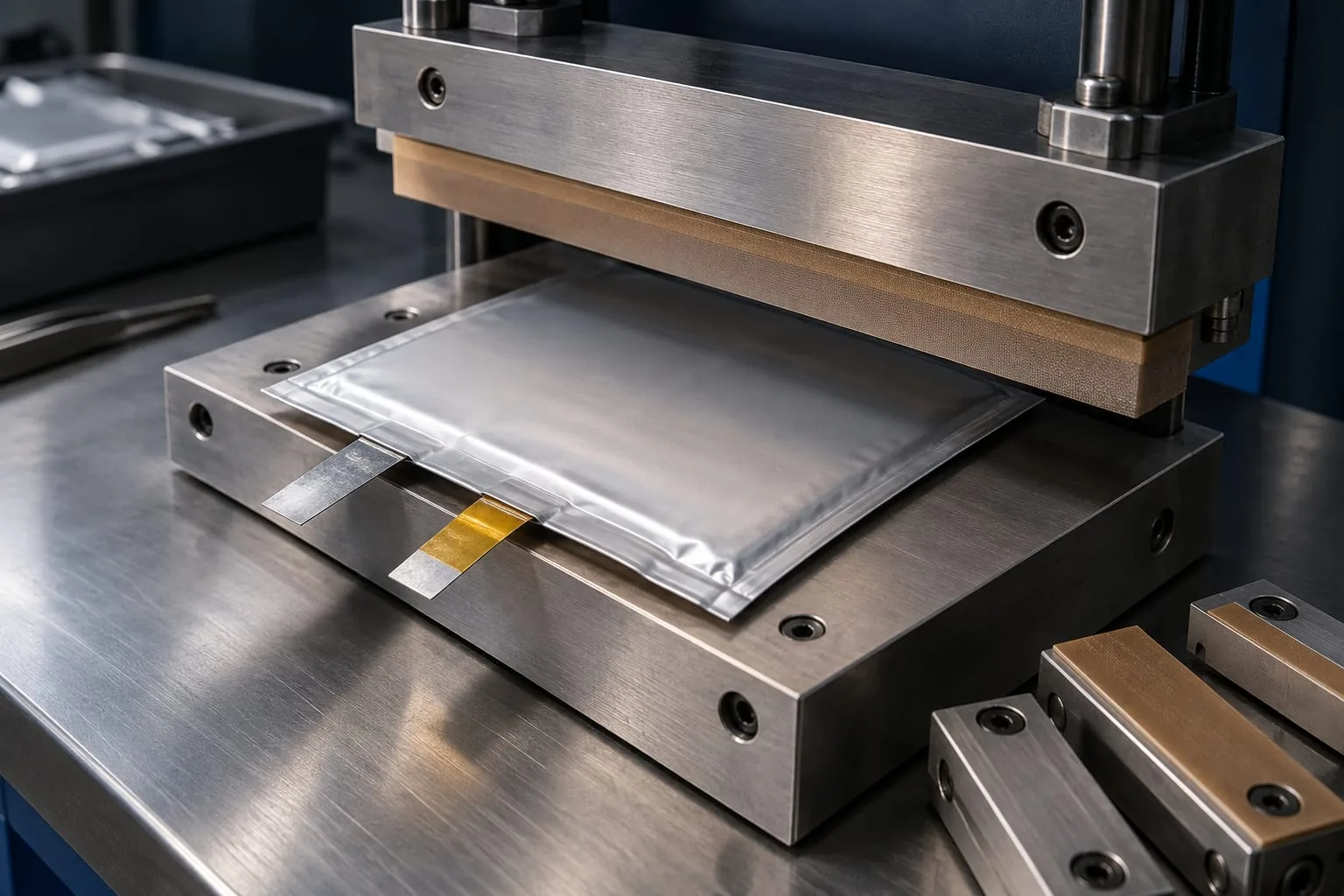
Sealing a pouch cell is a materials-and-interface problem, not just a matter of turning up heat. The laminate, lead exits, heated jaw surface, pressure and hold time all have to work together. A component that is suitable for one pouch format or sealing arrangement may be wrong for another.
For engineers and maintenance teams, the practical starting point is to map the seal zones and record the machine interface before ordering a replacement element, jaw cover or sealing bar. This keeps the discussion focused on the parts that actually contact the pack.
What must match in a pouch sealing process
The laminate is part of the specification
Pouch cells commonly use a flexible laminated case that is heat sealed at its edges. That is useful context, but it is not a universal production recipe. The laminate construction and sealant layer still need to be confirmed for the cell being made.
A published study of polymer-aluminium-polymer films for pouch lithium-ion batteries reports that the sealant layer thickness and material processing affect heat-seal strength. The practical implication is simple: do not select a heat-seal component from the outer appearance of the pouch alone. Record the film structure or supplier specification where available.
The EPO pouch-cell casing example shows why seal folding and dimensional control are considered together. Use it as background for the geometry discussion, not as a specification for a particular line.
Lead-throughs need their own seal zone
Tabs and leads interrupt an otherwise flat sealing path. They can change the local thickness, create a heat-sink effect and leave a narrow area where alignment and surface contact matter more than they do across the plain edge. The seal around each lead should therefore be treated as part of the component interface, not as an afterthought.
Map the pouch seal before specifying parts
Mark the top seal, side seals and lead seals on a drawing or a clean sample. Note where the heated jaw contacts the laminate, where the element sits in the jaw, and where a release or protective surface is needed. This map is more useful than a general request for a battery sealer because it identifies the actual heat-seal interface.
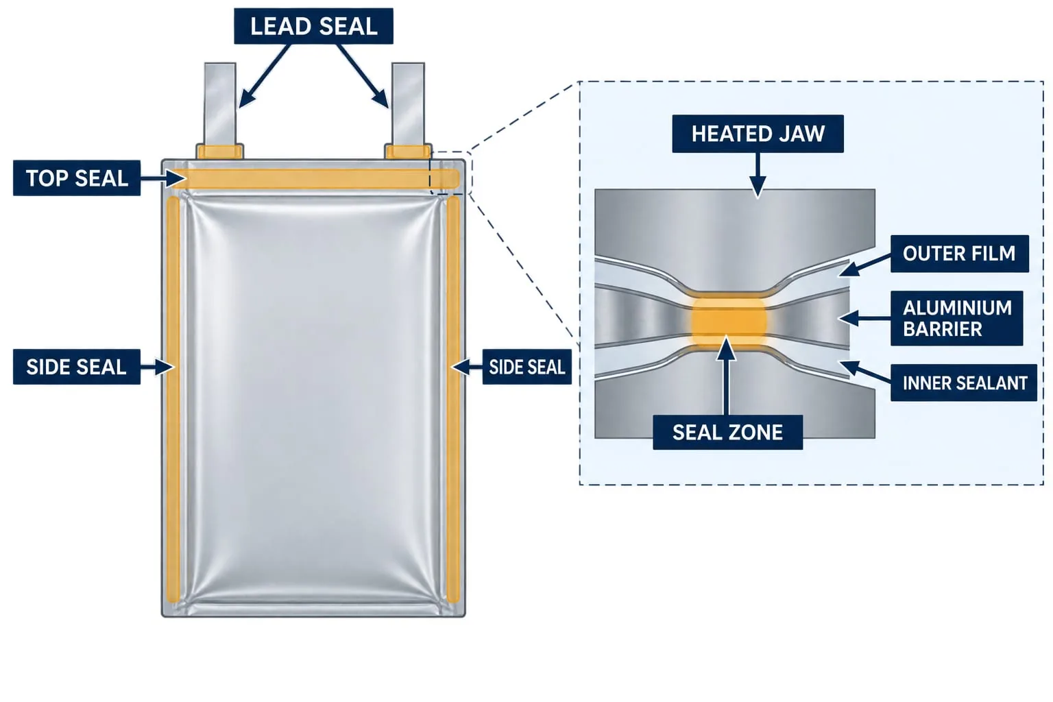 At minimum, record:
- the seal location and orientation;
- the usable seal length and width from the approved drawing;
- the lead or tab positions and the local stack-up;
- the jaw profile, element position and terminal arrangement;
- the existing PTFE cover, tape or other release surface; and
- any difference between the operator-facing and product-facing jaw surfaces.
These details help distinguish a replacement heat-seal element from a jaw, bar or covering issue. They also give a supplier enough context to discuss compatibility without guessing a machine model or a battery format.
Choose the component around the machine interface
Heating element and jaw geometry
The element must sit correctly in its channel or support and present a consistent heated path to the laminate. Check the existing element shape, length, terminals, insulation and retention method against the machine drawing or the removed part. If the installation uses a formed or non-standard profile, custom impulse heat-seal elements may be a more useful starting point than a generic catalogue description.
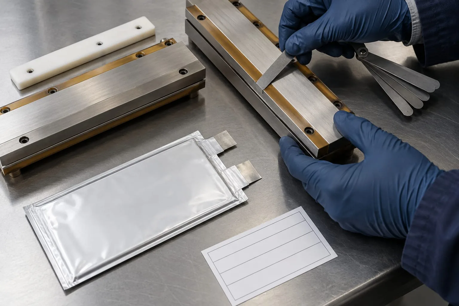
The jaw matters just as much. A sealing bar that is not parallel, or that has a damaged contact surface, can create uneven pressure even when the element itself is correct. HSC makes bands, elements and covers for, and recoats, sealing jaws and bars for component-level replacement and compatibility discussions; the final fit still depends on the dimensions and interface supplied for the application.
The protective surface has to suit the element arrangement, jaw geometry and maintenance method. A worn or contaminated cover can change release behaviour and make a good element appear to be failing. Where the installation calls for it, PTFE heat-seal tape can be considered as part of the heat-seal interface, subject to the equipment and laminate requirements.
Control heat, pressure and dwell together
There is no responsible universal temperature or dwell-time setting for every battery pouch. The RSC study on polymer-aluminium-polymer films reports that temperature and dwell time interact, while the useful process window depends on the film and the failure mode. Settings should therefore come from the laminate supplier, the equipment design and the customer’s own validation work.
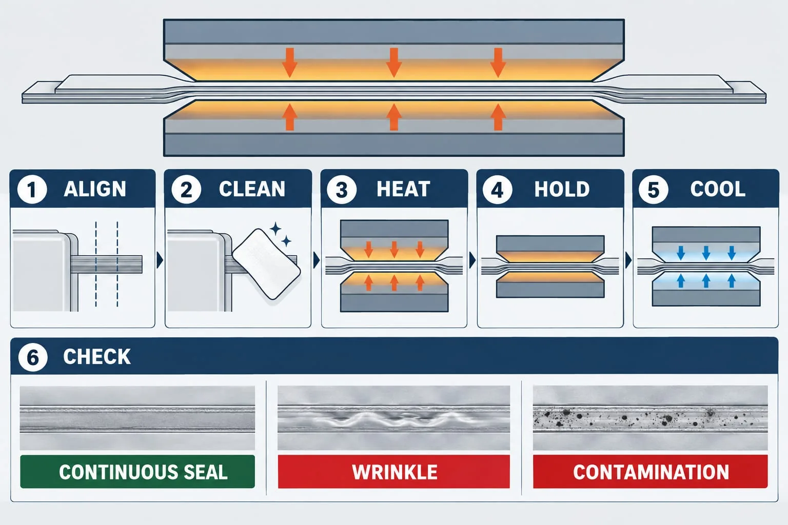 Treat the process as a controlled sequence: align the pouch and lead, clean the contact area, bring the jaws together, apply the approved heat and pressure cycle, hold for the specified time, then allow the seal to cool as required by the process. The order is useful; the numbers must be established for the specific materials and machine.
The Canadian Food Inspection Agency’s flexible retort pouch defects guidance is not a battery approval standard, but it is a useful general reference for clean seal areas, parallel surfaces, material compatibility and validation. It also reinforces a practical maintenance point: inspect filled or representative samples using the customer’s approved checks rather than treating a visual pass on an empty coupon as final proof.
Inspect the seal interface after a change
Inspection should cover the component and the result. Start with the jaws open and check for contamination, damaged covers, uneven contact and obvious loss of parallelism. Confirm that the element is retained correctly and that the lead area is not forcing the pouch out of position.
 After the approved trial cycle, inspect the seal for continuity, position, wrinkles, channel marks, contamination and any sign of delamination or incomplete bonding. Compare the result with the customer’s acceptance criteria and test method. Do not infer leak performance, peel strength or battery safety from appearance alone.
If a change affects the element, jaw surface, PTFE protection or pouch material, record the change alongside the sample result. This makes it easier to separate a component issue from a setting, handling or material issue during the next maintenance review.
What to send when requesting compatible parts
Heat Seal Components can discuss component compatibility for impulse, VFFS and flow-wrap sealing equipment, but a useful recommendation needs the actual interface details. Send:
- the equipment maker and model, if known;
- the seal location and a marked photograph or drawing;
- element dimensions, profile and terminal details;
- jaw or bar dimensions and photographs with the jaws open;
- the PTFE cover or tape arrangement;
- laminate or sealant-layer information where available; and
- the symptom, recent change and any approved trial result.
If the original part is unavailable, photographs of the installed channel, terminals, jaw face and sample seal are still useful. They allow the enquiry to stay grounded in the part that needs to fit rather than in an assumed complete machine specification.
Contact Heat Seal Components about the right sealing parts
Share the seal map, component photographs and the available machine or material information with Heat Seal Components. The team can then assess whether the enquiry is best matched to a heat-seal element, heating element, sealing jaw or bar, PTFE protection, or another compatible component within its confirmed offer.