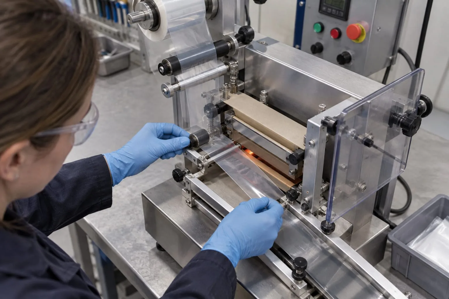
Compact automatic sealers still depend on a correctly matched heating and pressure assembly. A small footprint does not make every element, band, PTFE cover or jaw interchangeable. The safest way to order a replacement is to identify the sealing method, record the fitted component and check how the part mounts before requesting a quotation.
Heat Seal Components supplies heat-seal elements and wires, endless bands, sealing jaws and bars, PTFE coating and heat-seal tape, and custom heating elements. This guide explains what to record when the equipment is already on your line. It is not a guide to choosing a complete machine.
What a Compact Automatic Sealer Needs from Its Seal Assembly
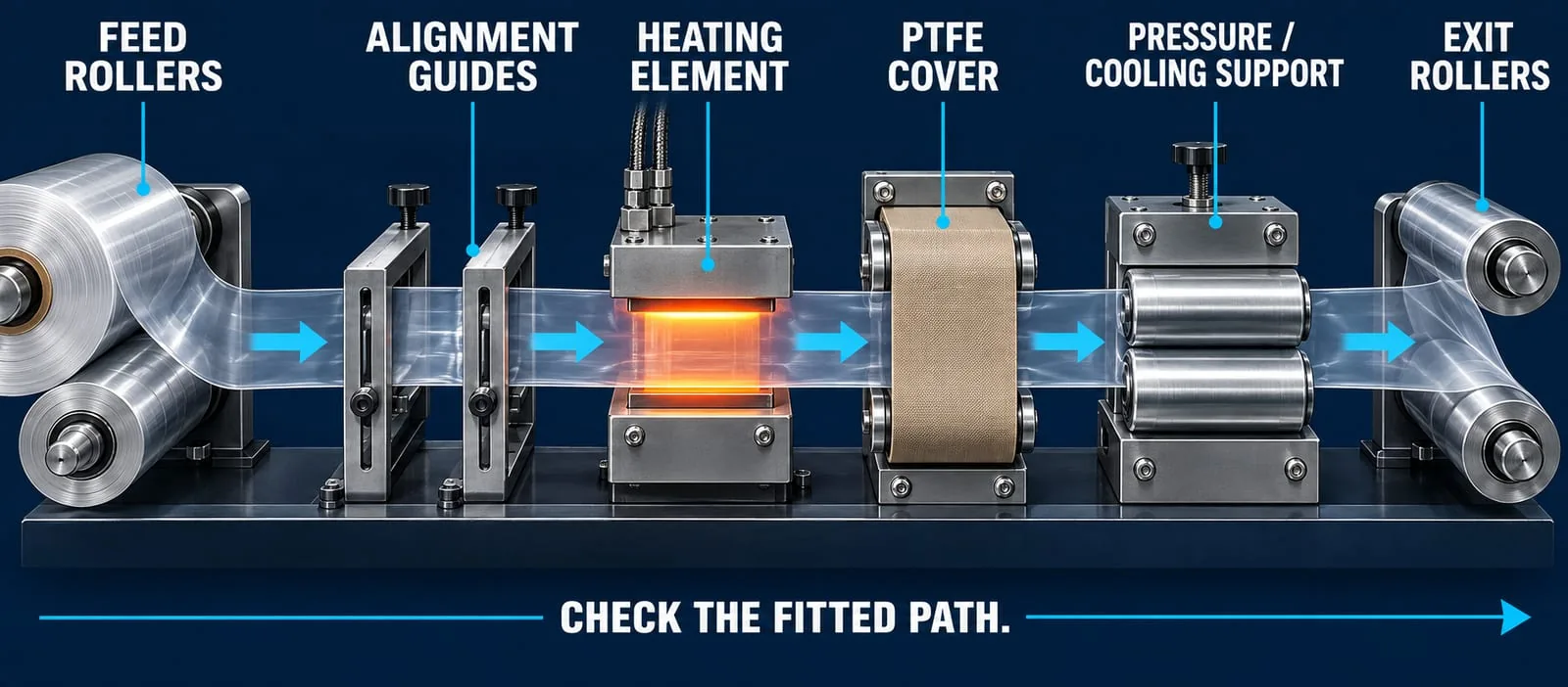
The seal assembly has to transfer heat and pressure through the intended part of the film or laminate. The key components are usually:
- A heating element or endless band with the correct working length, profile and electrical connection.
- A PTFE cover or tape that protects the heated surface and presents the right contact surface to the film.
- A pressure, cooling or support surface that matches the machine’s closing or conveying path.
- Mounting points, terminals, guides and clearances that fit the installed assembly.
The machine’s small size does not remove the need to confirm these details. Compare the fitted part with the supplier’s heat-seal elements range and request a custom impulse heat-seal element when a standard part cannot be verified.
Match the Component to the Sealing Method
Jaw or bar systems
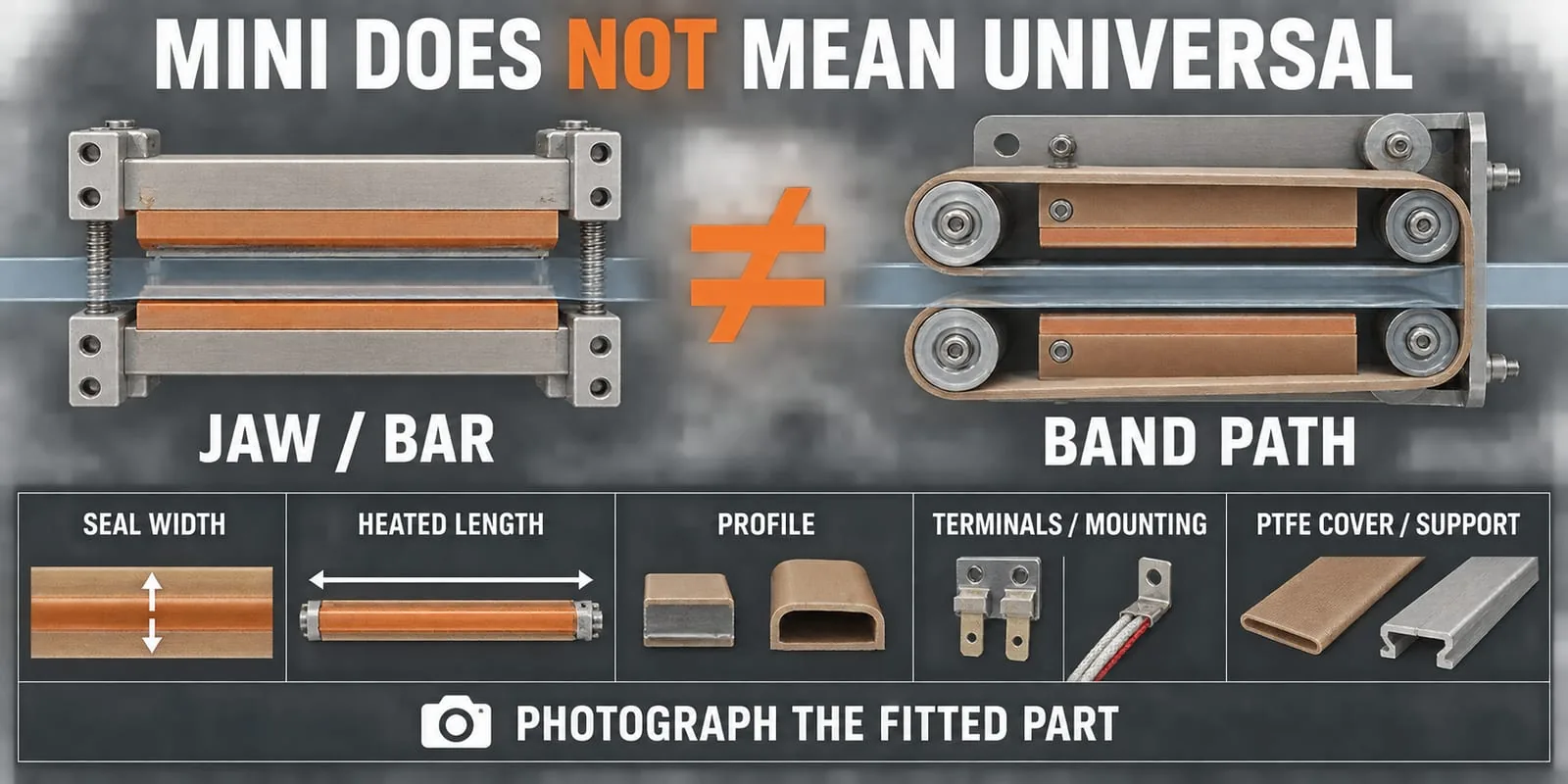
Jaw and bar assemblies bring two surfaces together around a defined seal area. Record the heated length, seal width, element profile, terminal position and the support or pressure material. A replacement that looks similar can still sit incorrectly if its mounting points or profile differ.
Heat Seal Components’ sealing jaws and bars can be considered when the installed assembly uses a bar or jaw path. Send a clear photograph of the fitted part, not just the machine name, so the working interface can be checked.
Continuous band systems
Continuous band systems carry the film through a moving seal path. In addition to the heated band, check the band route, guide rollers, PTFE protection and any cooling or pressure rollers. A band that is the right length but follows the wrong route can track poorly or damage the film.
Manufacturer information for continuous band equipment shows why the band path and protection should be treated as one assembly. Do not copy a temperature, speed or cooling value from another model. Use the machine’s instructions and confirm the result on the actual packaging material. Audion’s continuous band sealer information is a useful example of the components that sit around a moving band.
Record the Details Before Ordering
Take the following record while the fitted component is accessible and before removing anything:
- Machine make, model and, where available, serial or line reference.
- Seal width and heated length, measured from the installed part rather than guessed from the machine envelope.
- Element or band profile, terminal arrangement, mounting holes and any visible routing features.
- PTFE cover, tape or coating type and the condition of the support or pressure surface.
- A straight-on photograph, a side photograph and a photograph showing the part installed in the machine.
Keep the old part until the replacement has been checked. If the component is damaged, photograph the failure before cleaning it. Blackening, sticking, uneven wear and a broken element can each point to a different part of the assembly, so a photograph helps separate evidence from assumption.
Maintenance Checks for Compact Automatic Sealers

Maintenance should follow the equipment maker’s instructions and the site’s safe system of work. The Health and Safety Executive’s packaging machinery guidance highlights hazards during use and maintenance, while its work-equipment maintenance guidance covers isolation, stored energy, competent maintenance and records.
Isolate, cool and inspect
Before opening the sealing area, stop the machine, isolate it and apply the site’s lock-off procedure. Allow heated components to cool. Check that guards and interlocks are dealt with under the machine’s instructions. Never reach into a moving film path or assume that a stopped control panel has removed every hazard.
Check the consumable surfaces
Inspect the heating element or band, PTFE cover, tape, pressure pad, support surface and nearby rollers. Look for contamination, cuts, exposed wire, wrinkles, loose fasteners and uneven contact. Replace a worn cover or damaged element with a part that matches the installed assembly. Do not hide a tracking or pressure problem by adding more tape.
Maintenance intervals depend on the film, temperature, dwell or speed, cycle rate and working environment. The PackworldUSA preventative-maintenance guidance gives practical examples of these variables and the checks around PTFE strips, silicone surfaces and jaw alignment. The component supplier can help identify the replacement, but the site remains responsible for the machine’s safe maintenance procedure.
Verify the process after replacement
After a component change, run the machine according to its instructions and inspect representative seals. Check alignment, appearance and continuity before returning the line to normal production. Where the packaging process requires it, record the change and complete the site’s calibration or validation checks. hawo’s maintenance, calibration and validation service guidance explains why these activities are related but not interchangeable.
Troubleshoot Common Seal Defects
Weak or incomplete seal
Check that the element or band reaches the intended contact area and that the PTFE cover, pressure surface and closing path are in good condition. Confirm the film is aligned and that the machine is using its documented process settings. Do not increase heat before checking contact and support.
Scorching, sticking or film damage
Inspect the PTFE cover for contamination, wear or wrinkles. Check the element profile and the pressure surface. If the film is sticking, isolate the equipment before cleaning and identify whether the problem is local to the cover, the heat source, the pressure path or the material.
Uneven seam or tracking
For a jaw or bar, compare the two contact surfaces and mounting points. For a band path, check the guide rollers, band route and support surfaces. A clear installed-part photograph and a short record of the defect are more useful than a machine name alone.
Request a Component Compatibility Review
Send the machine make and model, fitted-part photographs, seal width, heated length, profile, terminals or mounting details, and the film or laminate application. Heat Seal Components can then review the relevant element, band, PTFE cover, tape, jaw or bar, and advise what further information is needed. Contact Heat Seal Components with the record before ordering a replacement.