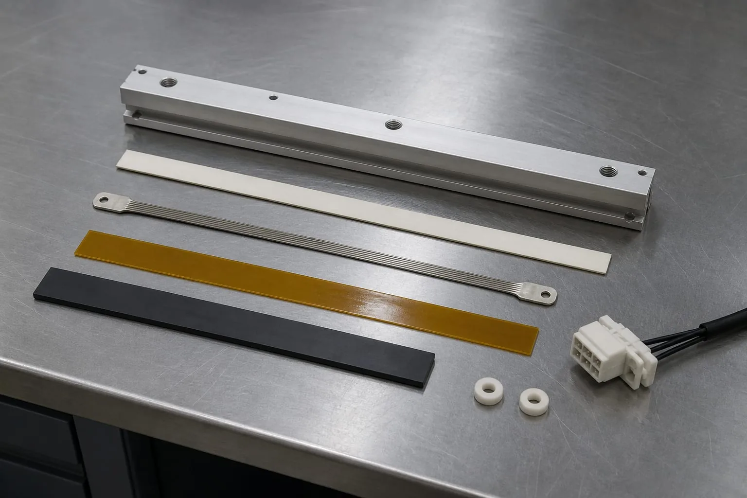
Identify the full sealing stack before specifying a replacement component.
A wire sealing machine creates a seal with a heated resistance element, pressure and controlled contact time. In an impulse machine, the element is normally energised for a short cycle and then cools while the jaws remain closed. Other equipment uses continuously heated jaws, bands or bars. The correct replacement therefore starts with the heating method, not the machine name alone.
For component enquiries, Heat Seal Components supplies heat seal elements and wires, including round wire, flat ribbon and made-to-specification parts for compatible packaging equipment. It does not supply the complete sealing machine. Before ordering, identify the active element, the support and cover system, the terminals, the control method and the condition of the opposing pressure face.
This guide explains what to record, how to check compatibility and how to separate an element fault from a wider sealing problem. It is written for maintenance technicians, packaging engineers, production managers and buyers who need a clear replacement specification.
Start with the heating method
Impulse sealing
An impulse sealer passes current through a wire or ribbon for a timed part of the cycle. The film is held under pressure as the element heats and during the cooling period. Fuji Impulse product information for a tabletop impulse sealer describes distinct heating and cooling stages and shows that even one machine family can accept different element widths. That is a useful reminder that a model name is only the first compatibility check.
A round wire usually creates a narrow seal or cut-and-seal line. A flat ribbon provides a wider contact area. The element may be straight, formed or fitted with purpose-made ends. Where the geometry or terminals are not standard, custom impulse heat seal elements can be made from a verified sample, drawing or full measurement set.
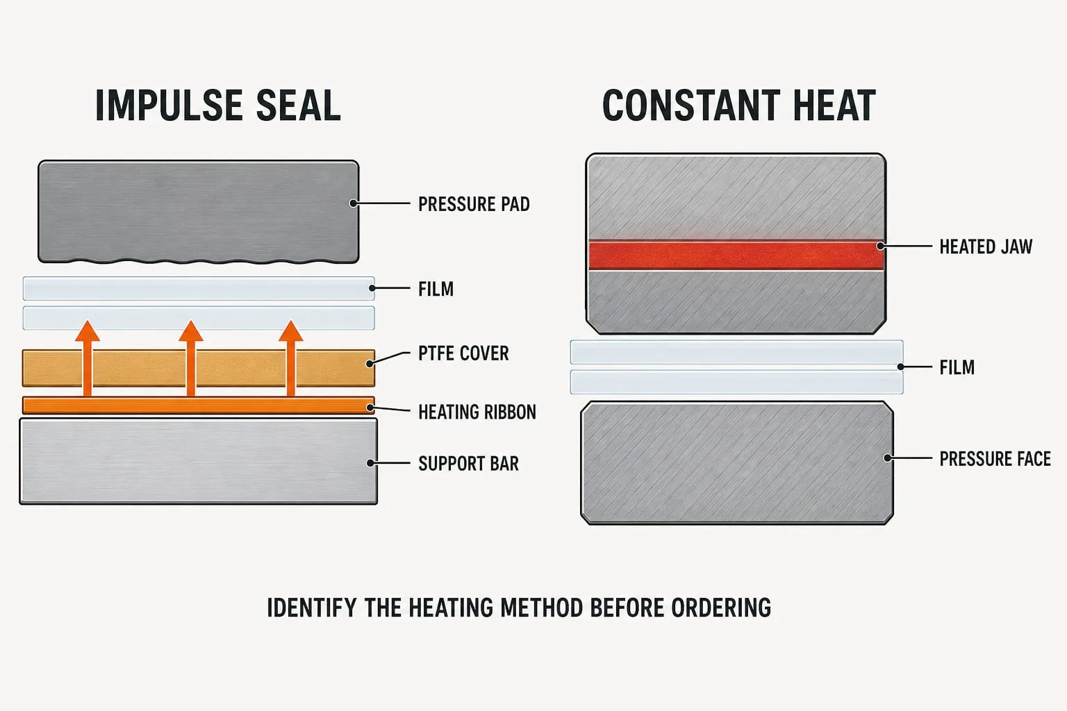 Identify whether the assembly uses an impulse element or a continuously heated jaw before ordering.
Constant heat and continuous systems
A continuously heated jaw or bar stays at its operating temperature rather than receiving only a short pulse. Continuous band and flow-wrap arrangements may also use heated bands, belts or formed components. Do not replace these parts with a generic impulse wire simply because both systems make a heat seal.
Confirm the actual heat source and the machine maker’s parts information. For a continuously heated assembly, the enquiry may relate to custom heating elements, a jaw or bar, a sensor position or a band system rather than a loose resistance wire.
Identify the complete sealing stack
The element works as part of a stack. A new wire can fail early or produce the same poor seal when a cover, support, terminal or pressure component is damaged.
- Heating element: round wire, flat ribbon, formed element, band or heated jaw.
- Release and insulation layer: the specified PTFE heat-seal tape, glass cloth or insulating strip.
- Support and pressure parts: the bar, jaw face, silicone pad or other resilient backing.
- Connections and tensioning: terminals, eyelets, clamps, springs and insulating washers.
- Control parts: timer, temperature controller, transformer, sensor and wiring specified by the machine maker.
Inspect sealing jaws and bars for contamination, distortion, sharp edges, loose fasteners and uneven pressure. Physical fit is not proof of electrical or thermal compatibility, and a correct element cannot compensate for a damaged support surface.
Record the replacement specification
Measurements and geometry
Isolate the machine, allow the sealing area to cool and photograph the part in position before removal. Measure the original without stretching or straightening it. Record dimensions in millimetres and distinguish the heated length from the overall end-to-end length.
- Overall length and active heated length.
- Round-wire diameter, or ribbon width and thickness.
- Every bend, notch, slot, hole and formed end.
- Terminal style, hole size and centre-to-centre fixing distance.
- Spring, clamp or other tensioning arrangement.
- Position and width of the cover, insulation and pressure pad.
If the element is broken, stretched or burnt away, also measure the mounting span and support bar. Add a simple dimensioned sketch with one fixed reference point. Photographs should show the complete assembly, both ends and close views of the terminals.
Machine and electrical details
Record the manufacturer, model, serial number, sealing station and whether the machine uses a single or double seal. Include the supply, element resistance or power information only when it is available from the rating plate, drawing, manual or a competent test. Do not infer a resistance value from appearance.
Resistance changes with material, cross-section and active length. A part can fit mechanically but draw the wrong current or heat unevenly. If the original specification is unknown, send the old element and machine details rather than choosing by length alone.
Check compatibility by machine type
Bench and industrial impulse sealers
Check the usable seal length, element profile, end construction, fixing span and the timer or controller arrangement. Cut-and-seal versions may use a shaped element or a combined profile. Never substitute wire for ribbon, or ribbon for wire, without verifying the jaw, cover system and electrical circuit.
Vacuum packers
Vacuum pack sealing elements are normally tied to a specific bar arrangement, terminal pattern and cover system. Record which bar and sealing position is involved. On some machines, the wire, PTFE cover and pressure profile are treated as related wear parts, so inspect them together.
VFFS, flow-wrap and continuous equipment
Identify the sealing station, component path, tracking or tension arrangement, seal pattern and operating method. These systems may use bands, formed heaters or heated jaws. A search term such as wire sealing machine does not prove that a wire is the correct component for the station.
Troubleshoot the whole sealing stack
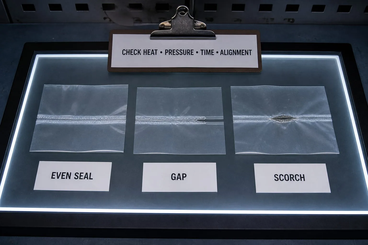 Compare the seal evidence before increasing settings or replacing the element.
Start with a controlled seal sample and compare it with the approved production standard. Check heat, pressure, contact time, cooling and alignment as a group. Increasing the heat setting can hide a pressure or timing problem and may shorten component life.
Gap or cold section
A repeated gap can indicate a broken element, poor terminal connection, damaged controller output or contamination. It can also come from a low pressure area, a worn pad or a distorted jaw. Check continuity only with the component isolated and follow the machine maker’s test procedure.
Scorching, sticking or a narrowed seal
Local scorching may point to excessive settings, a hot spot, poor tension or a damaged cover. Sticking can result from torn, contaminated or misaligned cover material. An IMPAK impulse-sealer manual instructs users to keep the sealing platform clean, replace torn cover material and disconnect power during servicing.
Short element life
Look for over-tension, restricted thermal movement, sharp edges, loose terminals, wrong cross-section and damaged insulation. Henkelman maintenance guidance for its vacuum packing equipment advises cleaning the bar and replacing the sealing wire and PTFE cover as related wear parts. Follow the procedure for the actual machine rather than treating that advice as universal for every design.
Replace and commission safely
Maintenance must be planned and carried out by competent people. HSE maintenance guidance says equipment should be made safe before work starts, moving plant should be stopped, power supplies should be isolated where required, accidental reconnection should be prevented and hot parts should be allowed to cool. The site risk assessment and the machine manufacturer’s instructions take priority over this general guide.
- Isolate and lock off the machine using the approved site procedure.
- Allow the sealing assembly to cool and confirm that stored energy cannot move the jaws.
- Photograph the original orientation, terminals, covers and fixings.
- Clean and inspect the support, pressure face, insulation and connections.
- Fit only the verified component without stretching, twisting or sharply bending it.
- Reassemble the specified cover and pressure parts, then check clearances and alignment.
- Run the manufacturer’s controlled commissioning checks and inspect trial seals before production.
Stop if the replacement heats unevenly, the controller behaves unexpectedly or the seal is outside the approved standard. Do not bridge a broken element, alter its active length or keep raising settings to force a result.
What to send Heat Seal Components
For a useful compatibility review, send the machine make and model, sealing station, full measurements, terminal details, clear photographs, any verified electrical information and a sample or drawing when the part is non-standard. State whether the fault is a gap, scorch, sticking, breakage or short service life.
You can contact Heat Seal Components with the evidence and the required quantity. The team can review the component specification and quote for suitable wires, ribbons, formed elements, related covers or sealing components. Unknown details should be marked as unknown rather than guessed.